Welcome, Guest
Username: Password: Remember me

TOPIC: 1971 Glasspar Newport Cruiser - Rejuvenation

1971 Glasspar Newport Cruiser - Rejuvenation 3 months 3 weeks ago #149488

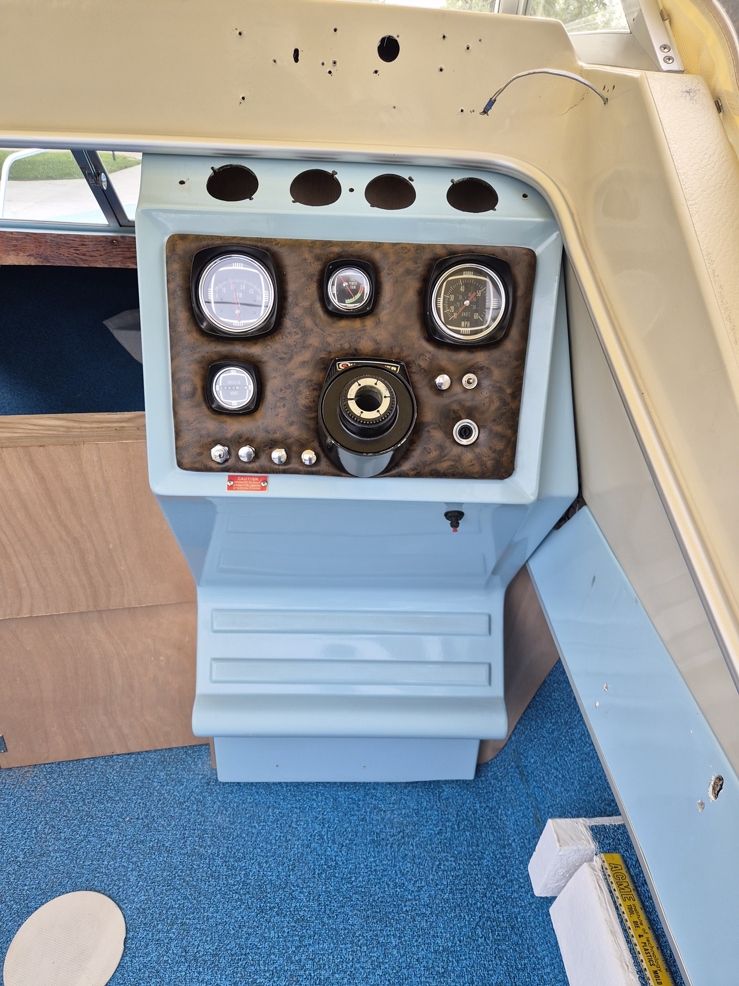
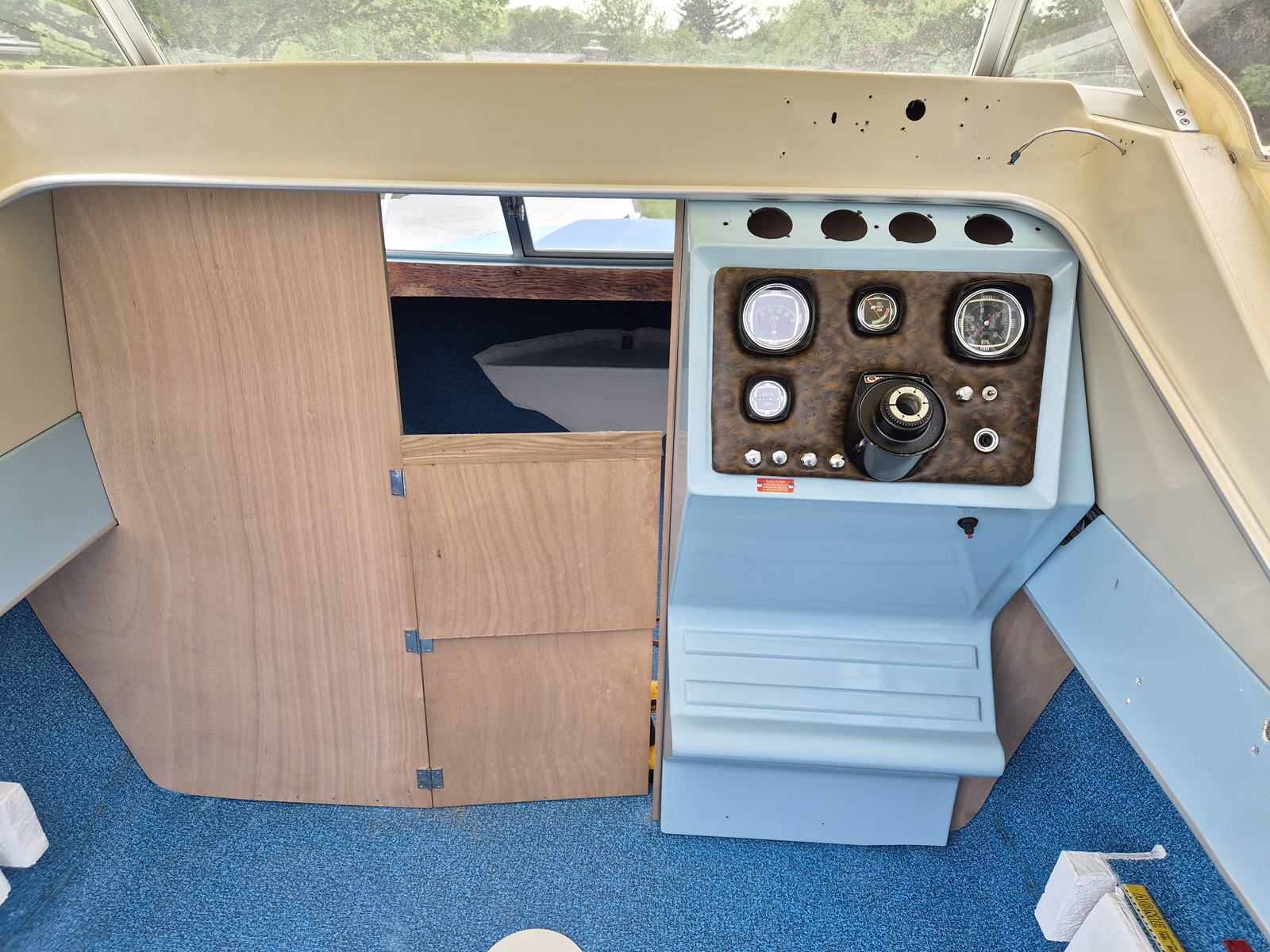
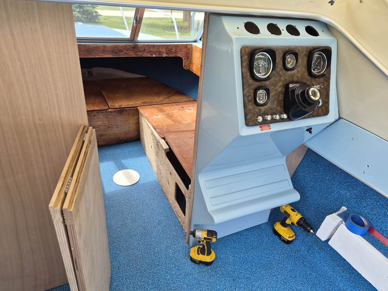
The console looks mahvelous!
That burlwood Naugahyde screams Disco-Fiber.
The following user(s) said Thank You: Larsspar

Please Log in or Create an account to join the conversation.

1971 Glasspar Newport Cruiser - Rejuvenation 3 months 3 weeks ago #149489

Looks like the weatherman just bought you some more time before the lakes will be ready.

Please Log in or Create an account to join the conversation.

1971 Glasspar Newport Cruiser - Rejuvenation 3 months 1 day ago #149505

  • Larsspar
  • Larsspar's Avatar Topic Author
  • Offline
  • Senior Boarder
  • Senior Boarder
  • Posts: 248
  • Karma: 5
  • Thank you received: 21
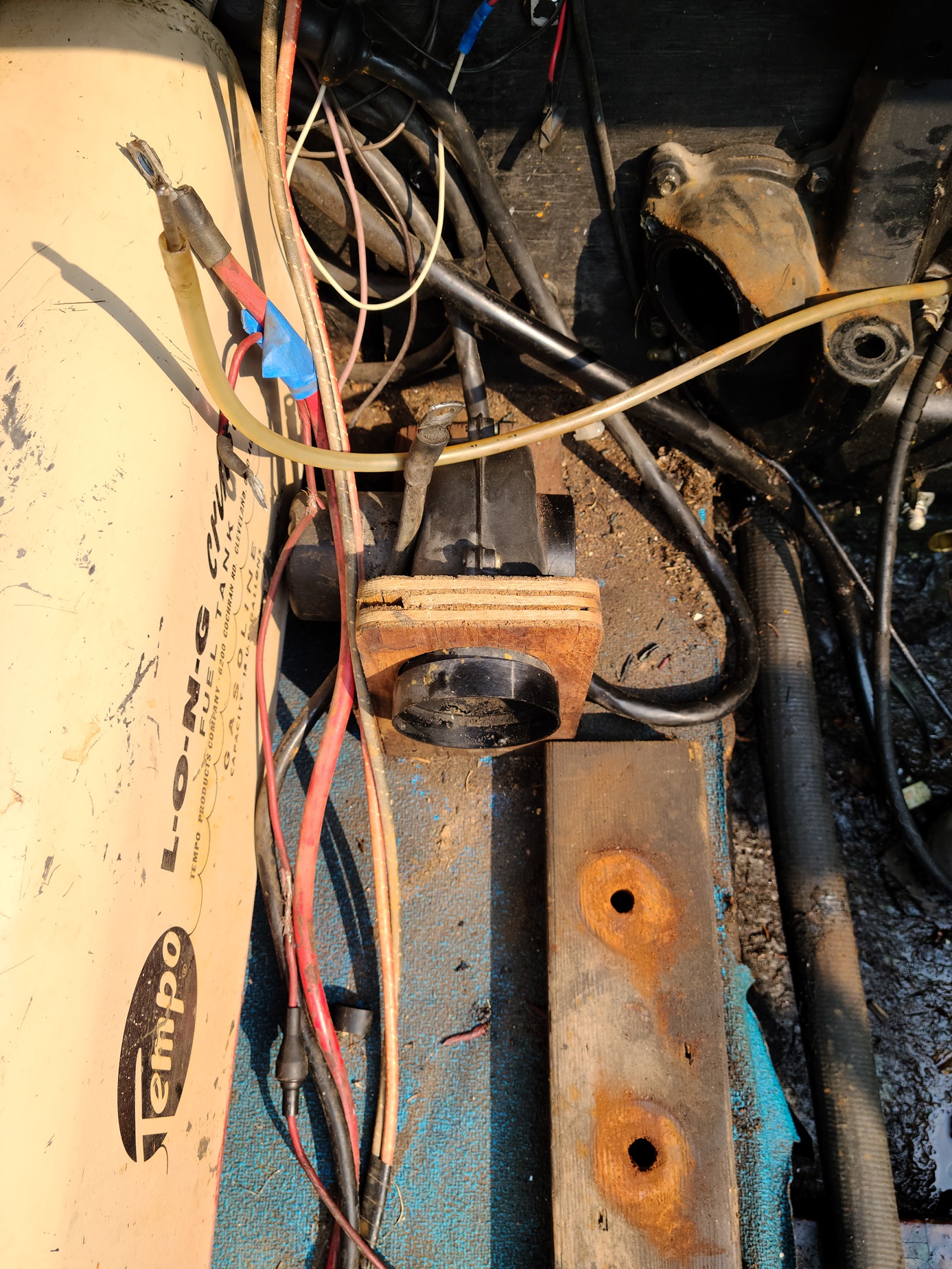
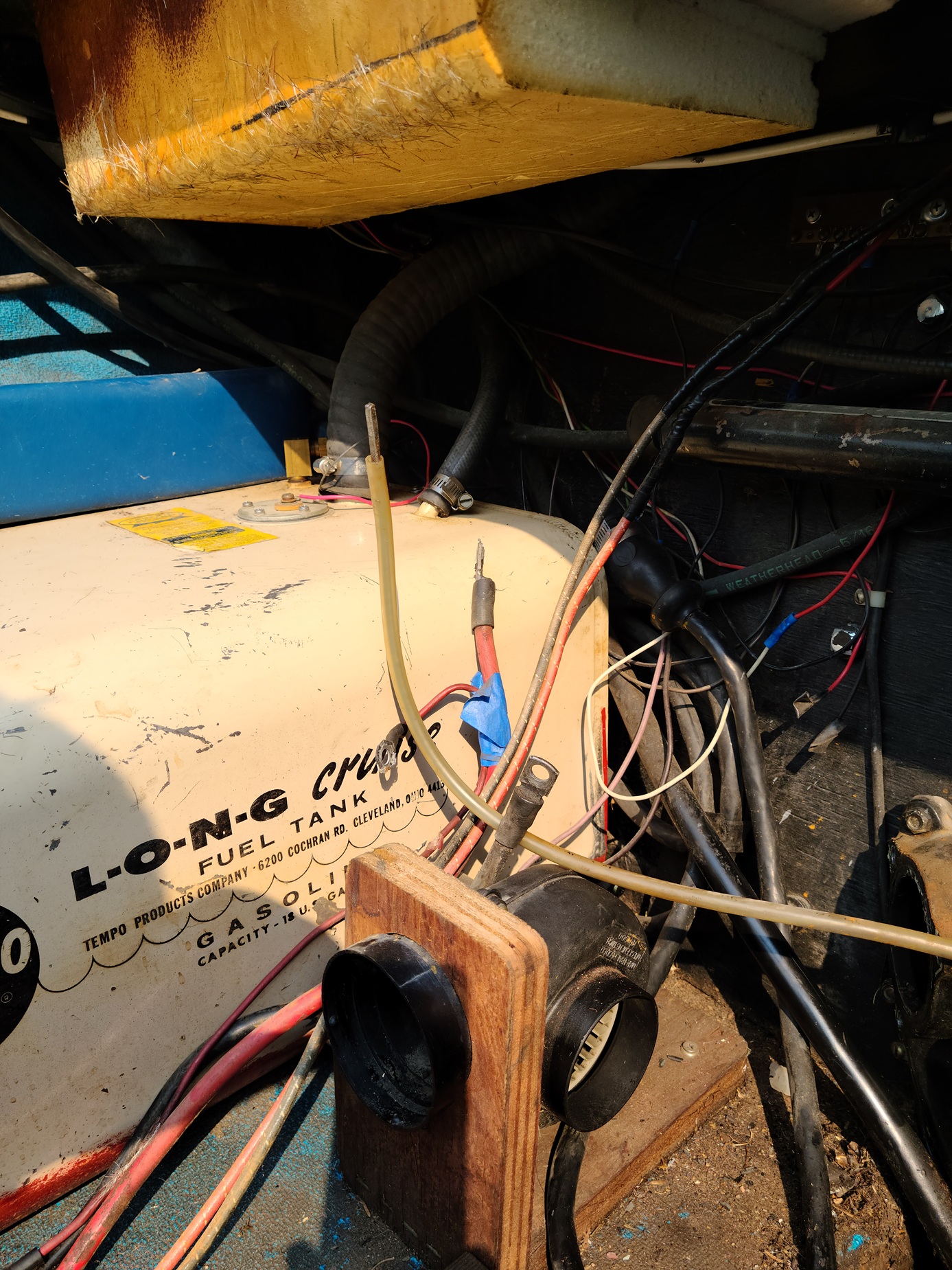
Looked at the original factory bilge blower.


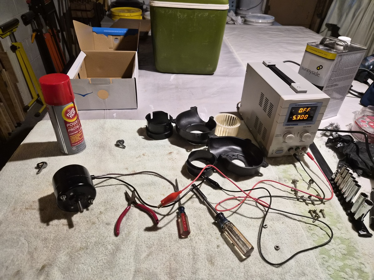
I connected it to a car battery, and it worked well. I decided to clean and rebuild it.


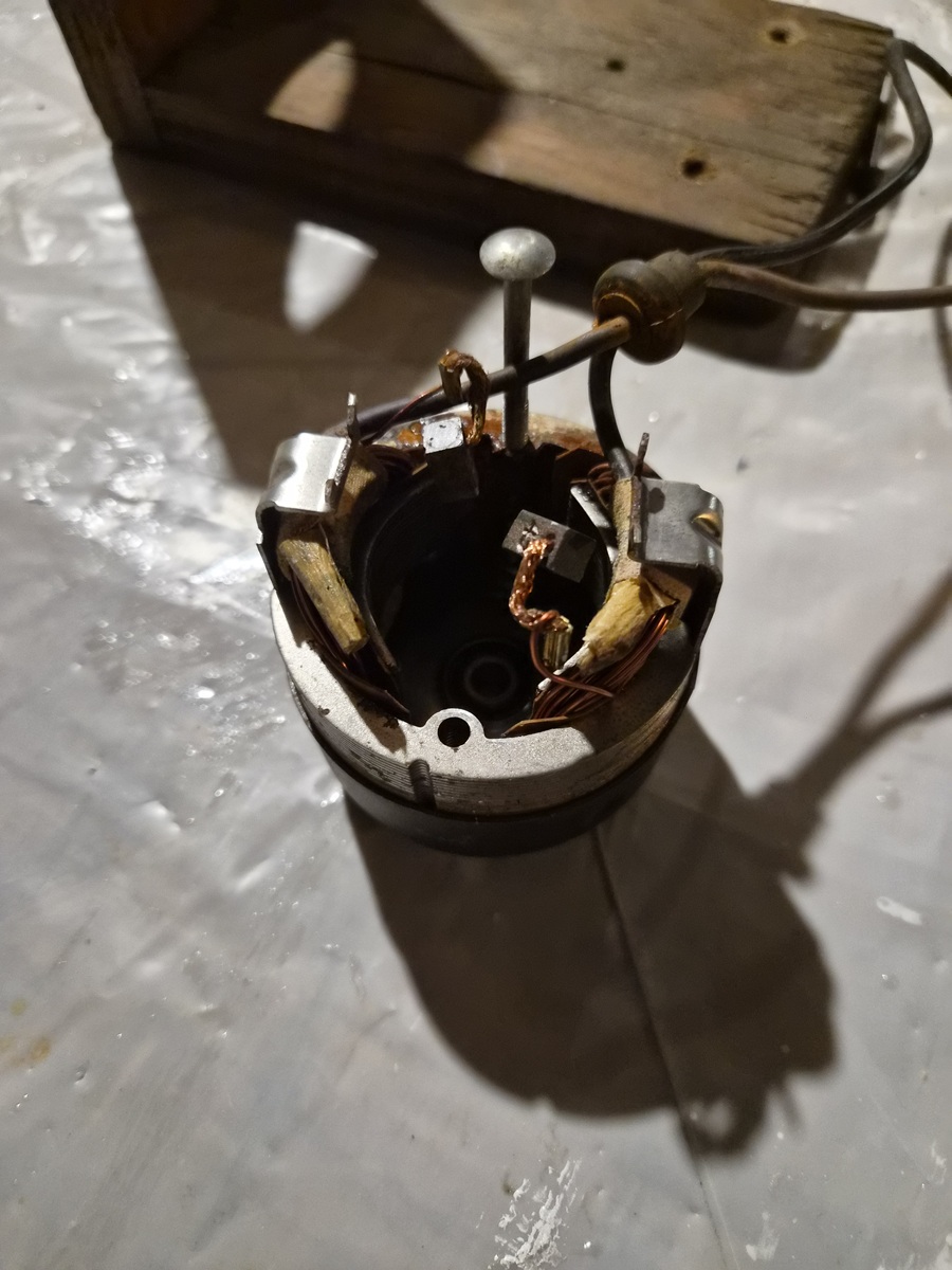
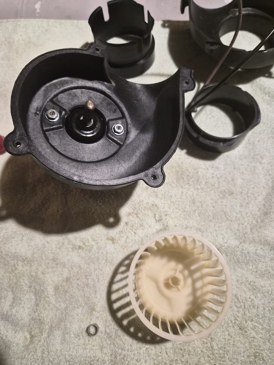
Disassembly of the electric motor was a little challenging due to minor corrosion.


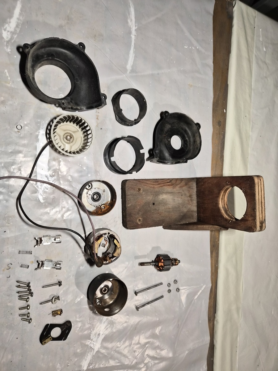
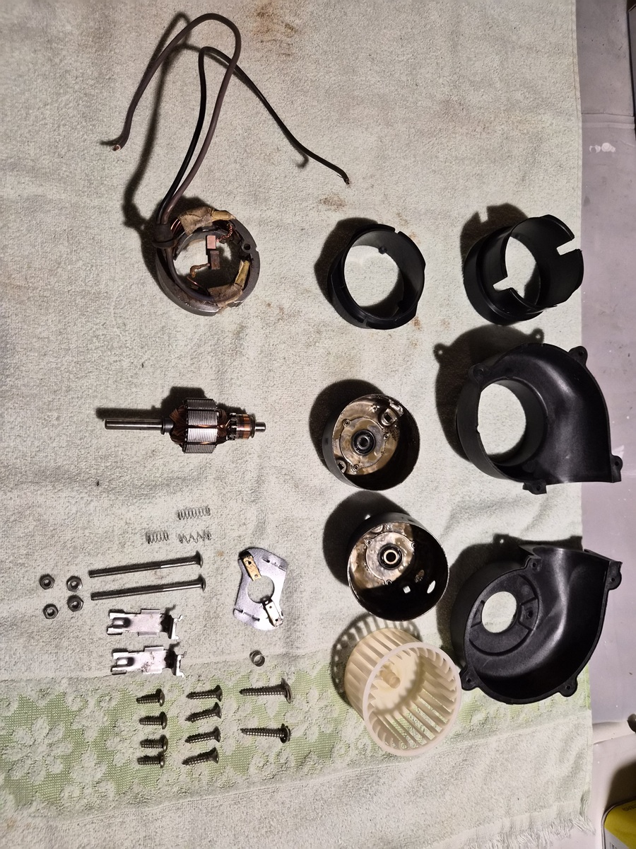
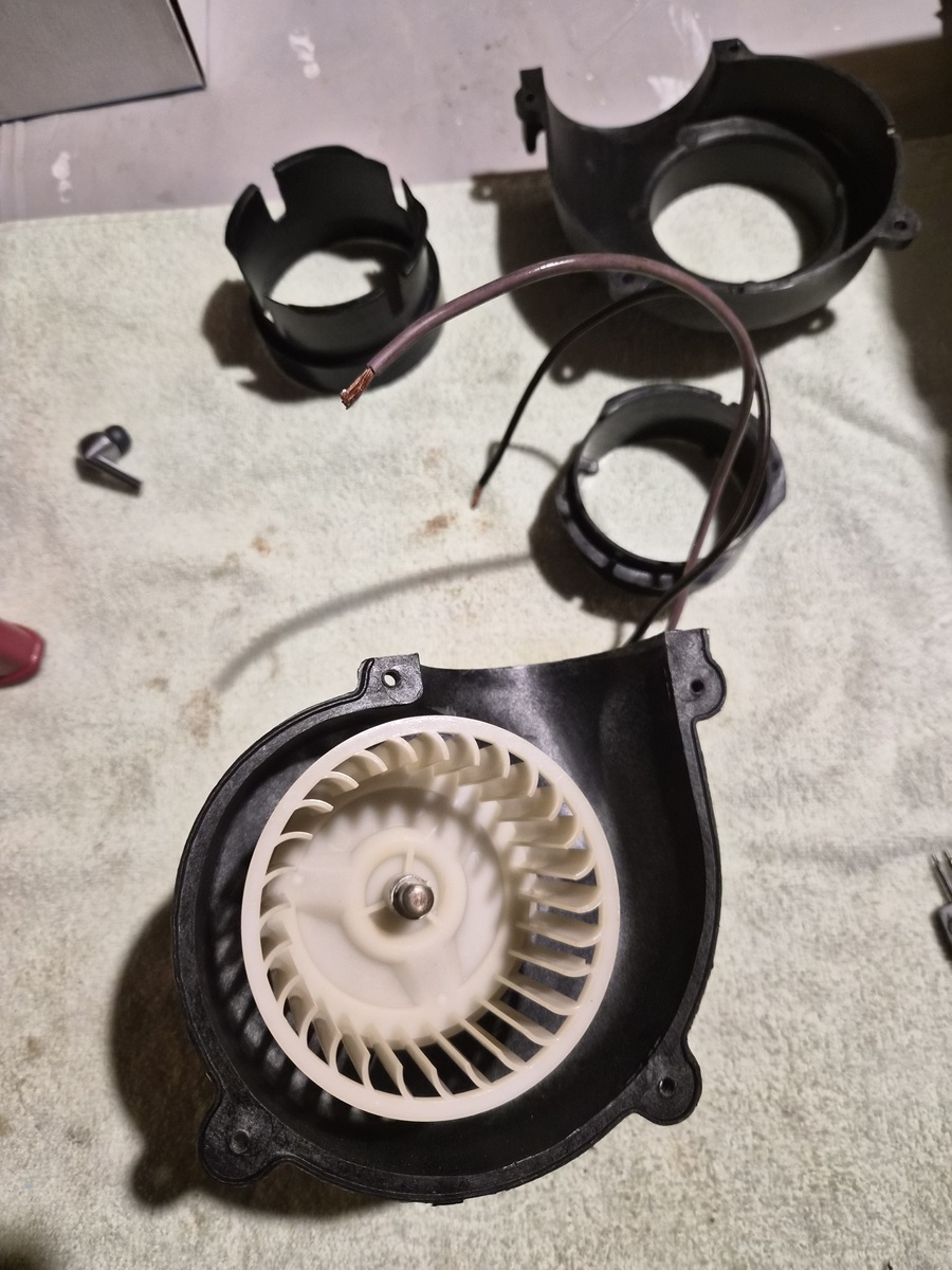
Components disassembled, ready for cleaning and inspection. I got a kick out of the one-inch-thick plywood used to make the blower mounting bracket.


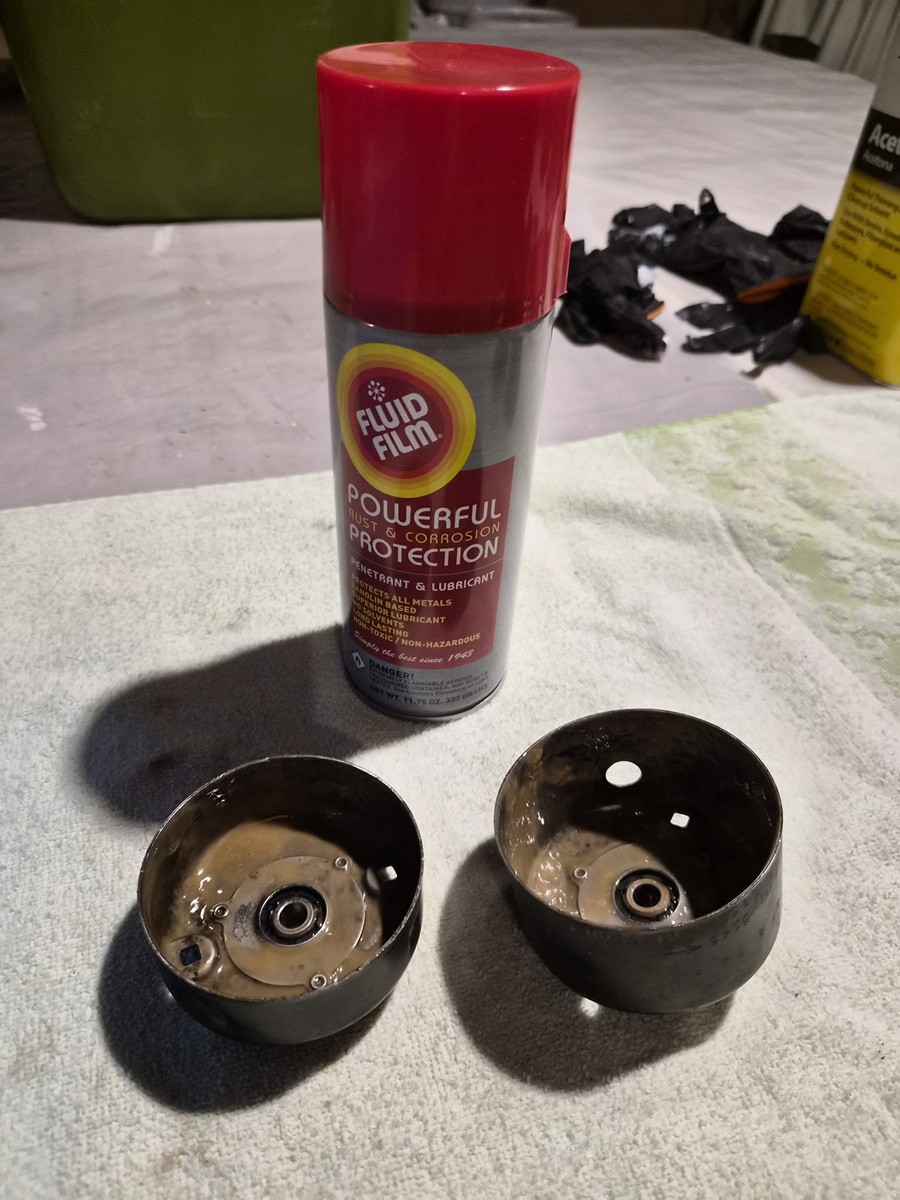
I used a rotary wire brush on a drill along with steal wool to remove light corrosion from the inside of the motor housing. I then applied a coating of Fluid Film for future protection.


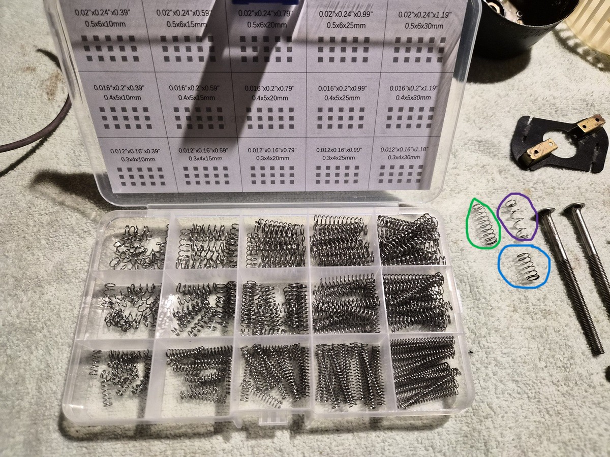
One of the motor brush springs had partially corroded. I picked this stainless-steel spring kit up from Amazon for $9. These springs were a little heavier than the original motor brush springs, so I combined a portion of a new spring (purple circle) with the good remaining piece of the old spring (blue circle) which made a workable solution. Original usable good spring. (green circle)


All components cleaned up and ready for reassembly. I ran the plastic parts through the dishwasher which left them looking Brand New. The motor has bronze shaft bearings which I applied Marine grease to before assembly.


Electric motor reassembled and tested. It runs smoothly, quietly, and most importantly coolly.


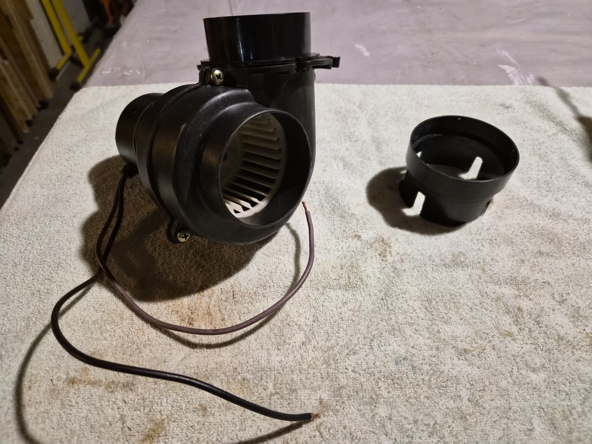
Began reattaching the blower housing to the motor. Used Loctite Blue on the nuts.


The fan or squirrel cage slips onto the motor drive shaft, and a steel collar is slipped on the fan to hold it in place.


Outer housing and blower manifold screwed in place.


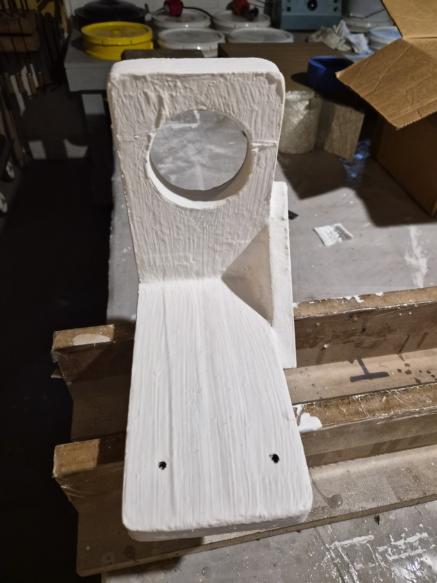
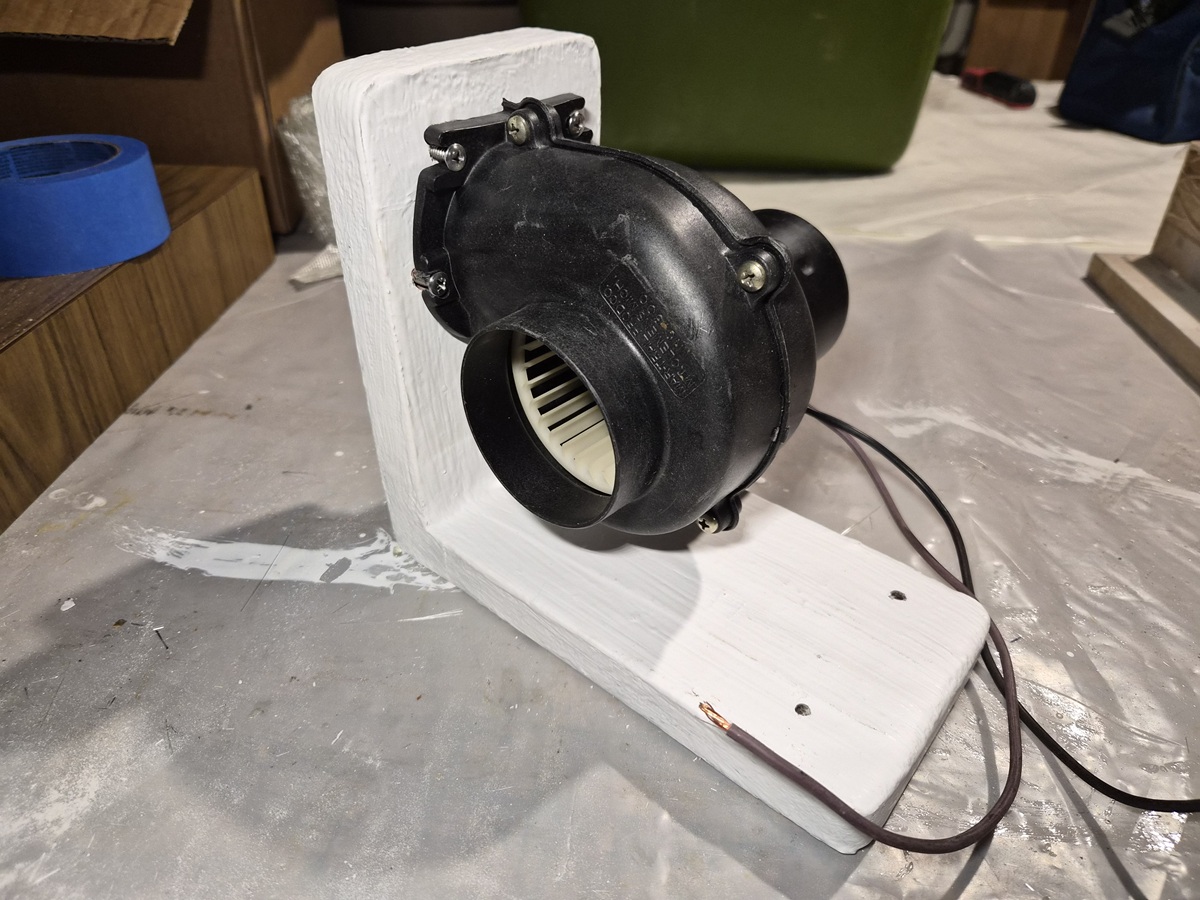
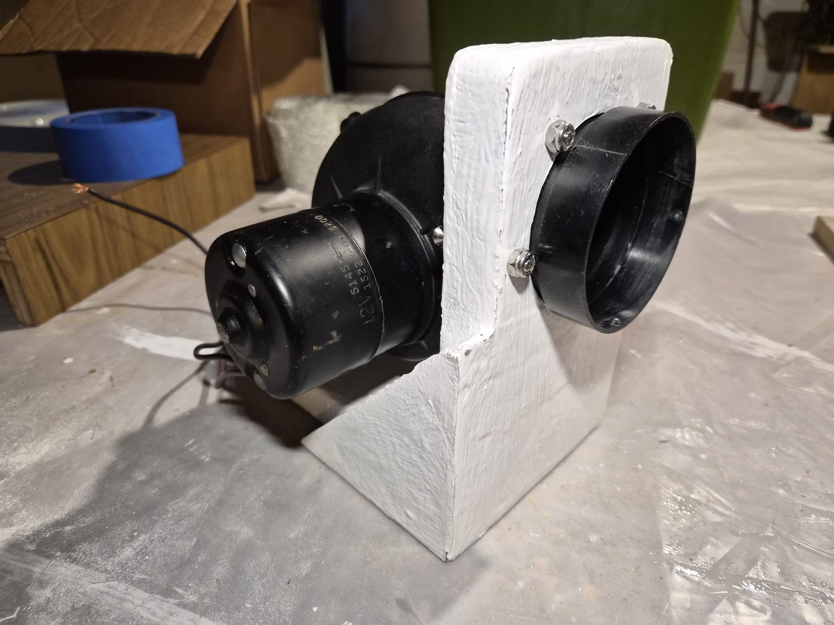
The base was originally stapled together. I took it apart and sanded each component. The side brace was originally made of half inch plywood and was not in the best shape, so I replaced it with a three-quarter inch piece of plywood. I screwed the pieces together using coating deck screws. I then filled all imperfections with polyester structural repair putty, a couple coats of polyester laminating resin, a layer of fiberglass and finally a couple coats of gelcoat. Not really pleased with my brush strokes.


Blower motor installed. Ready to go to work.


It runs so well that the exit airflow CFM might be high enough to pick up half-a-knot if I turn it on while underway. ;)

Please Log in or Create an account to join the conversation.

1971 Glasspar Newport Cruiser - Rejuvenation 3 months 14 hours ago #149507

  • Larsspar
  • Larsspar's Avatar Topic Author
  • Offline
  • Senior Boarder
  • Senior Boarder
  • Posts: 248
  • Karma: 5
  • Thank you received: 21
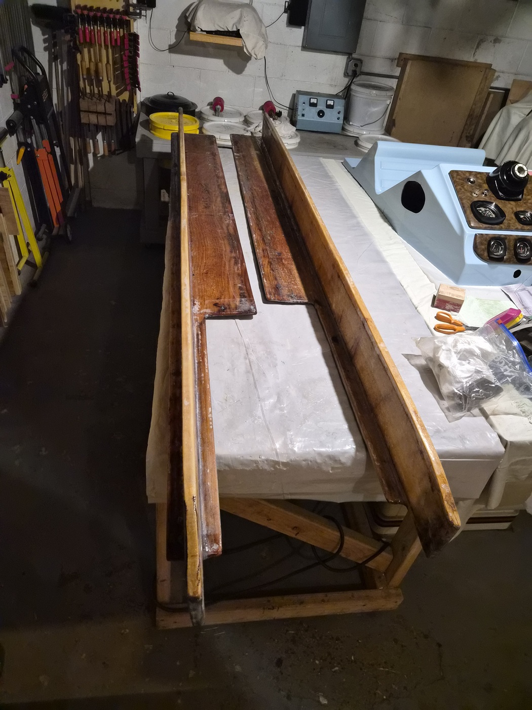
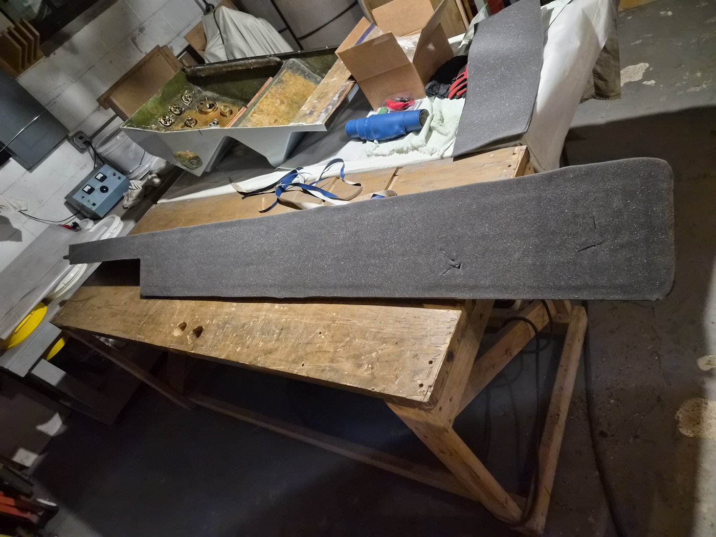
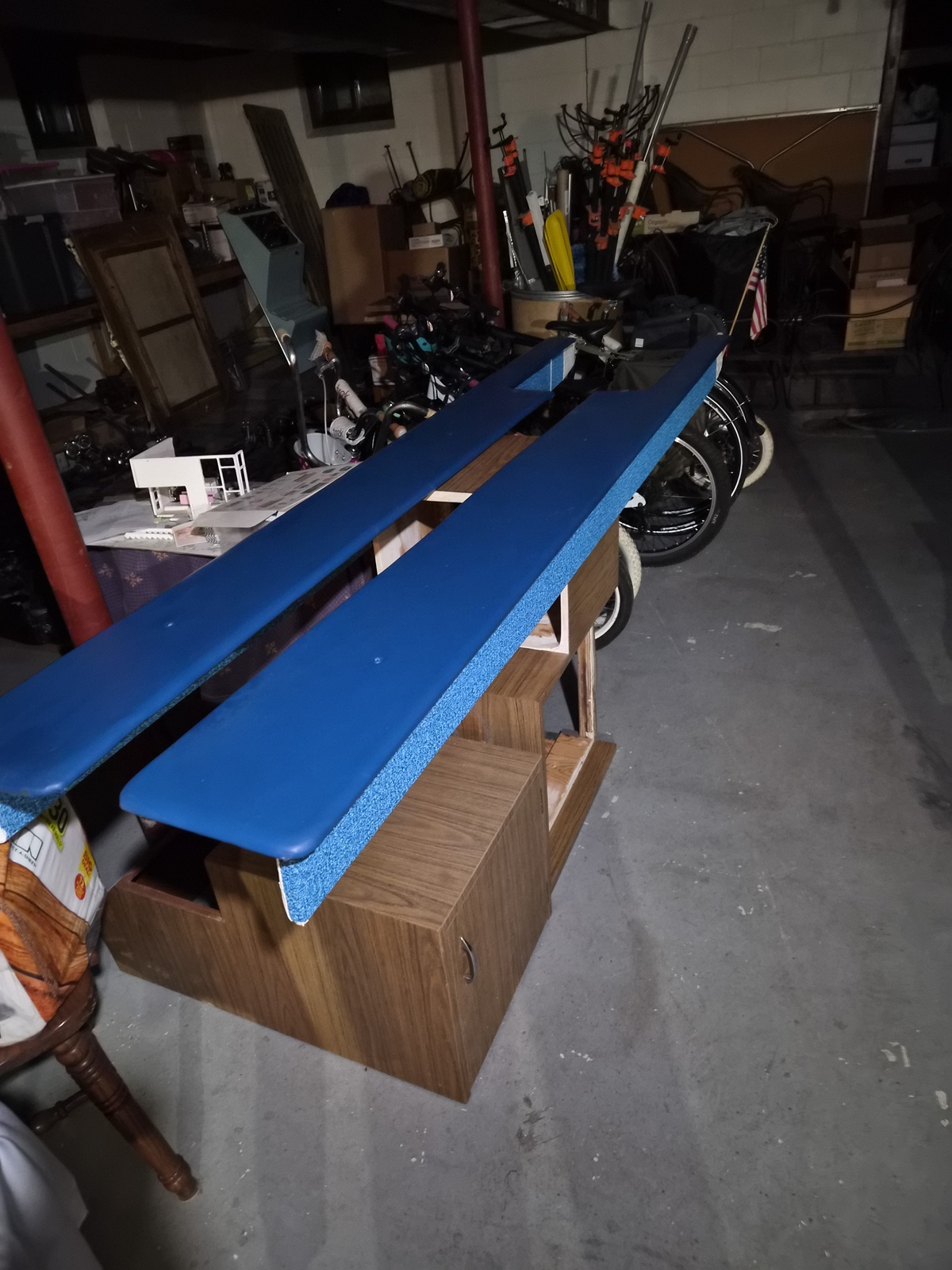
One of the bigger projects I've been advancing is the refurbishment of the ski shelves. They were a bit cupped and warped. Still, they showed little sign of decay.


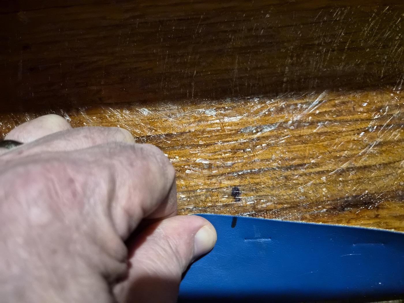
I started by making a few witness marks of the Naugahyde vinyl and ski shelf wood to assist with reinstallation. I then carefully pried out the staples from the Naugahyde and removed the Naugahyde and foam. The foam was discarded.


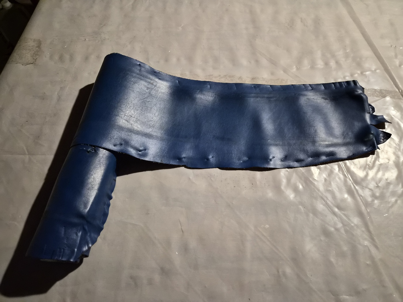
The original Naugahyde vinyl is still in very good shape, very soft and flexible. I cleaned the back side of each piece and set it aside.


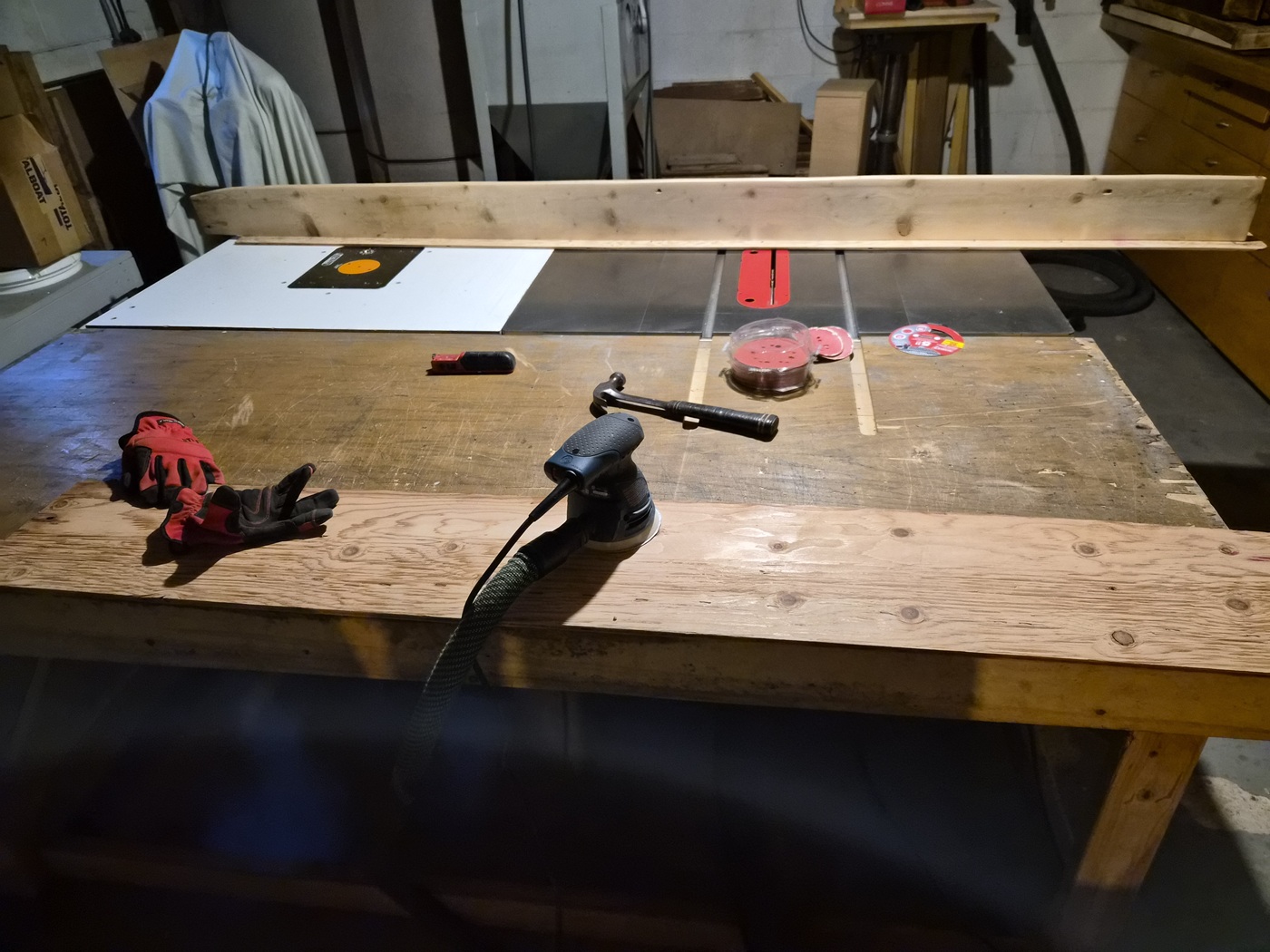
I gave each ski shelf a good sanding with 80-grit on the random orbital sander.


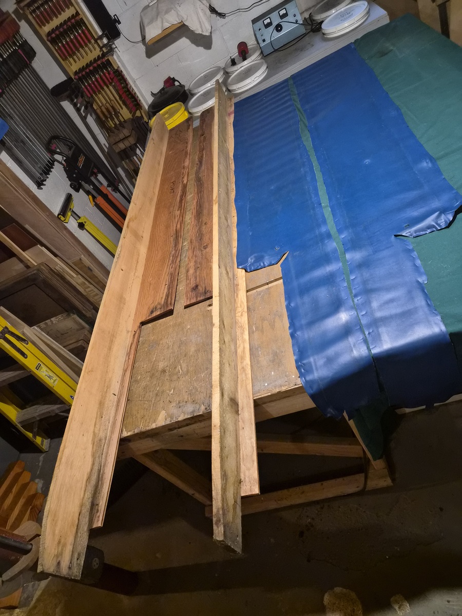
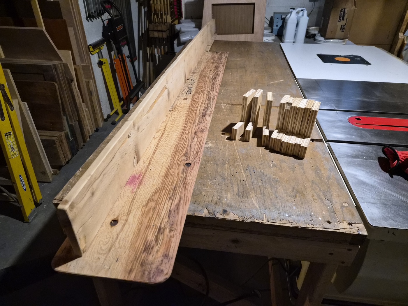
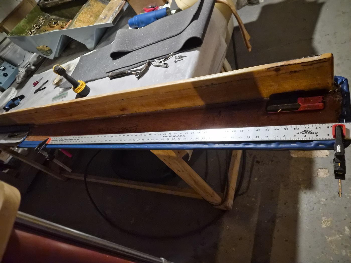
I made a series of right-angle clamping jigs to assist in correcting the cupping and warping of the wood.


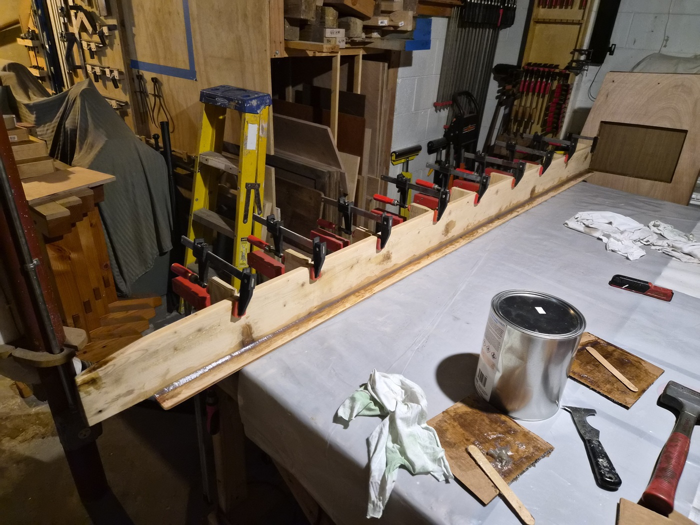
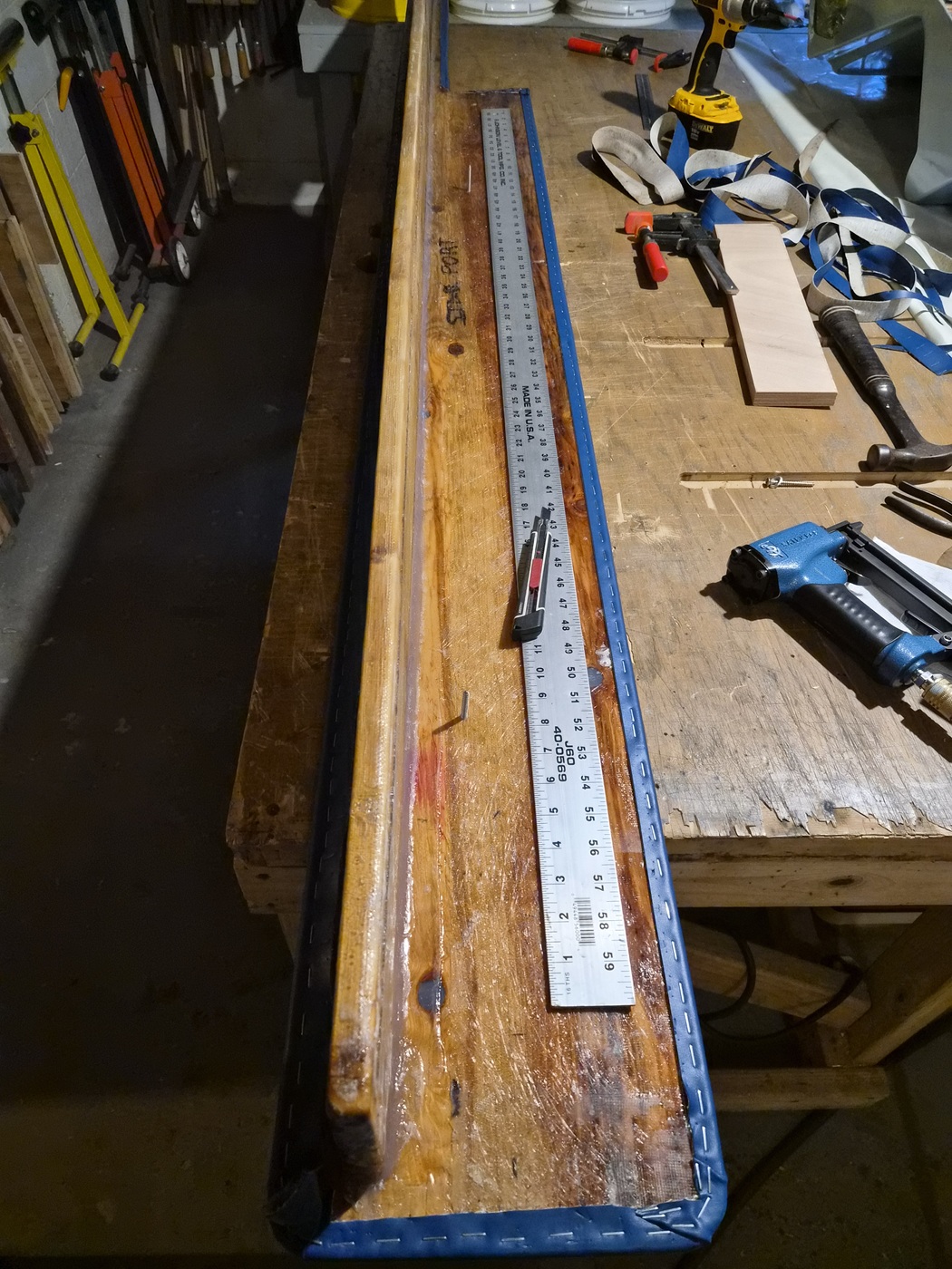
The jigs were clamped to the ski shelf and the flat worktable which assisted in squaring the wood. I then started the fiber glassing process by using polyester structural repair putty to fill imperfections in the wood and create rounded fillets on the 90-degree corners.


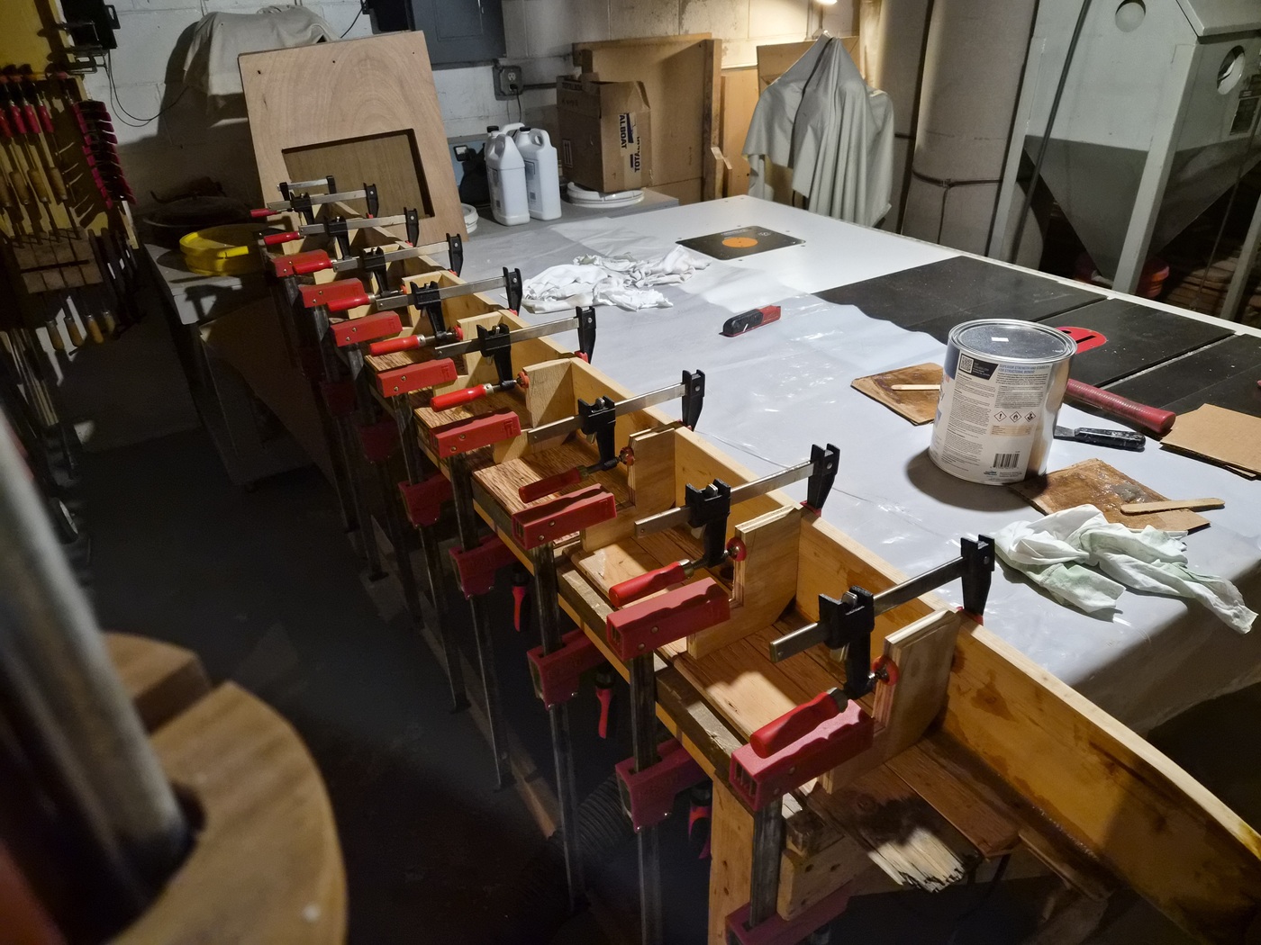
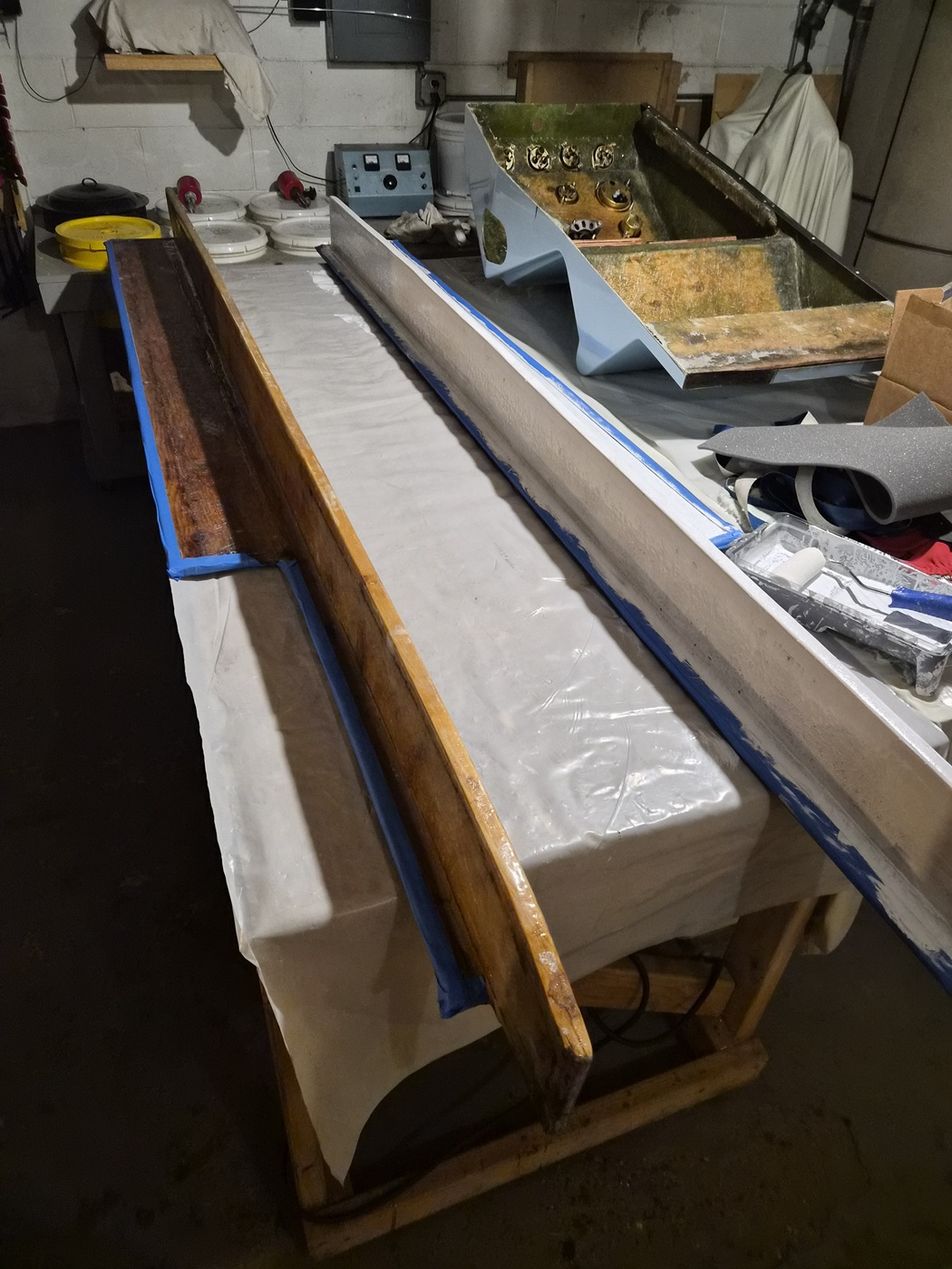
View of the jigs clamped to the worktable. Notice also how I relieved the corners of the jigs so they would not disturb the polyester structural repair putty fillet at the 90-degree corner.


With the jigs in place, I was able to fiberglass one side of a ski shelf at a time. The polyester laminating resin and fiberglass once dry, did a great job holding the wood 'nearly square' while adding rigidity and moisture resistance. Both shelves, although not perfect, are much closer to square now.


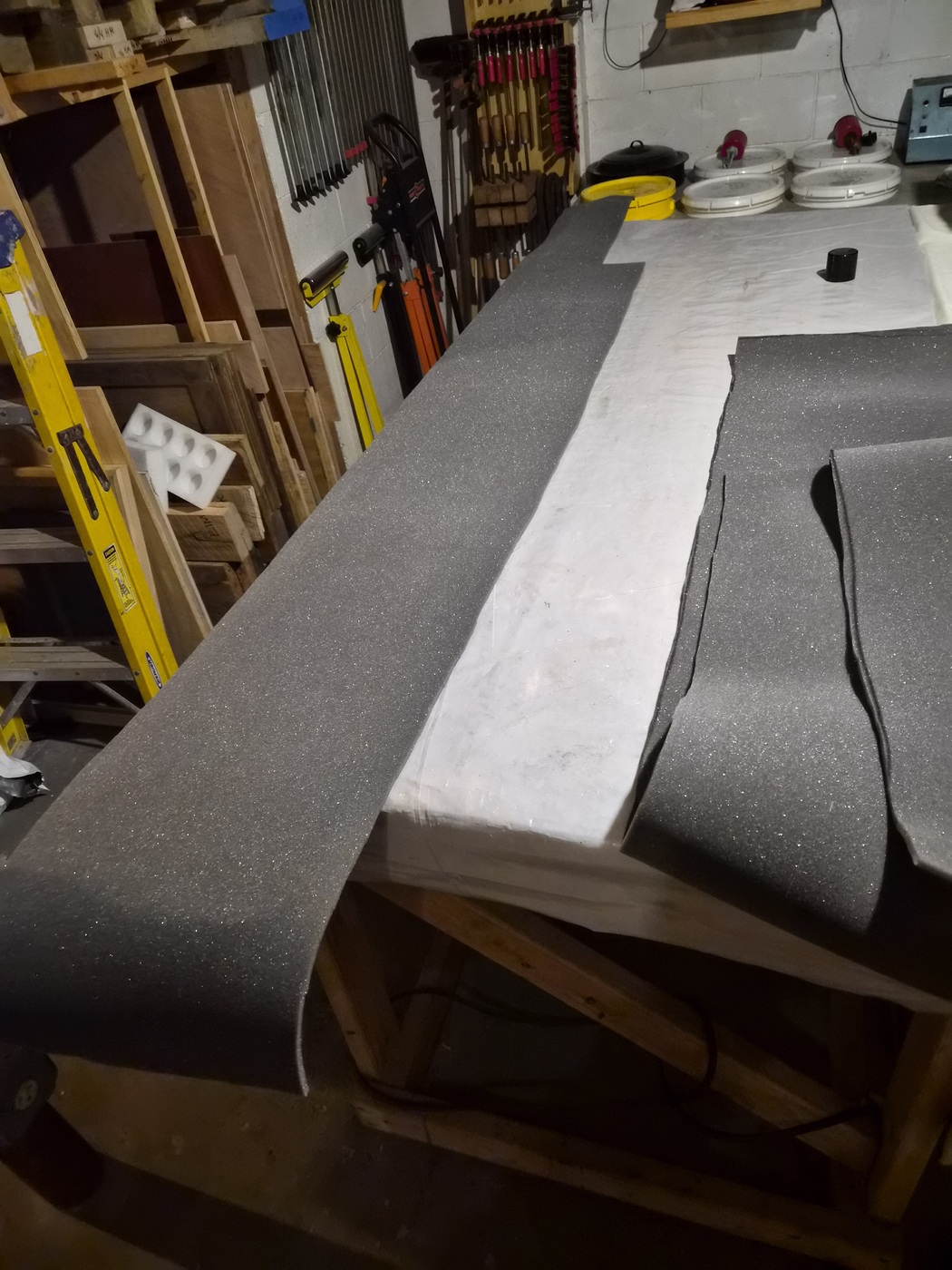
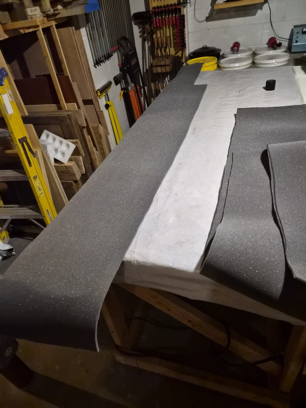
Rough cut new upholstery foam for each ski shelf outer face.


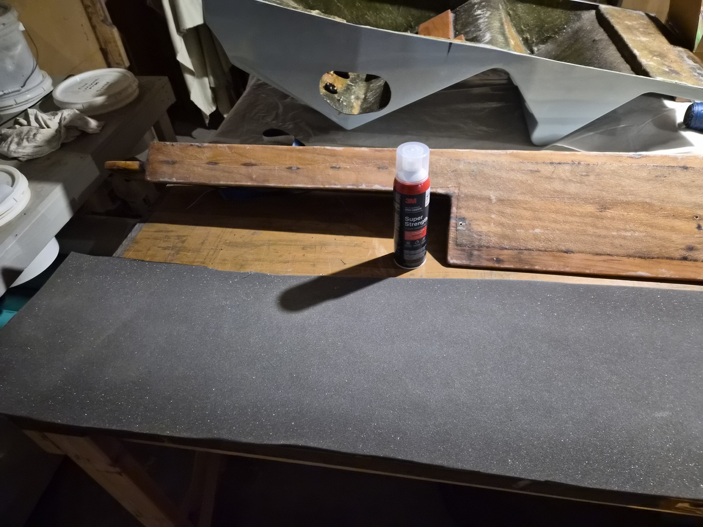
I applied a light coat of 3M 77 spray adhesive to the ski shelves and foam and applied the foam to the ski shelves.


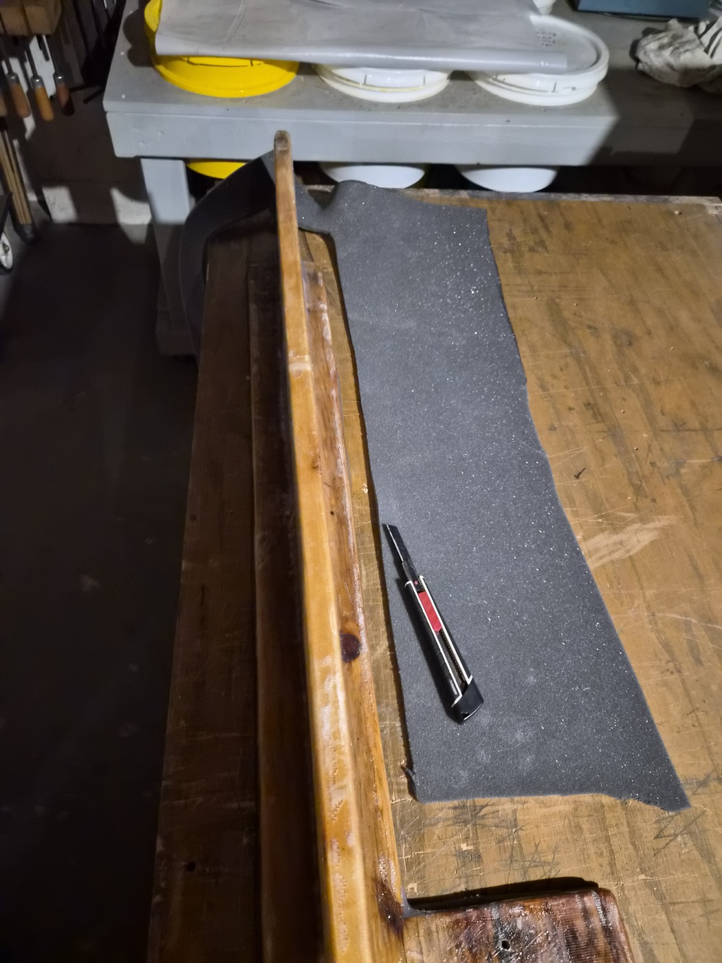
Once dry, I used a razor to trim the excess foam from each ski shelf.


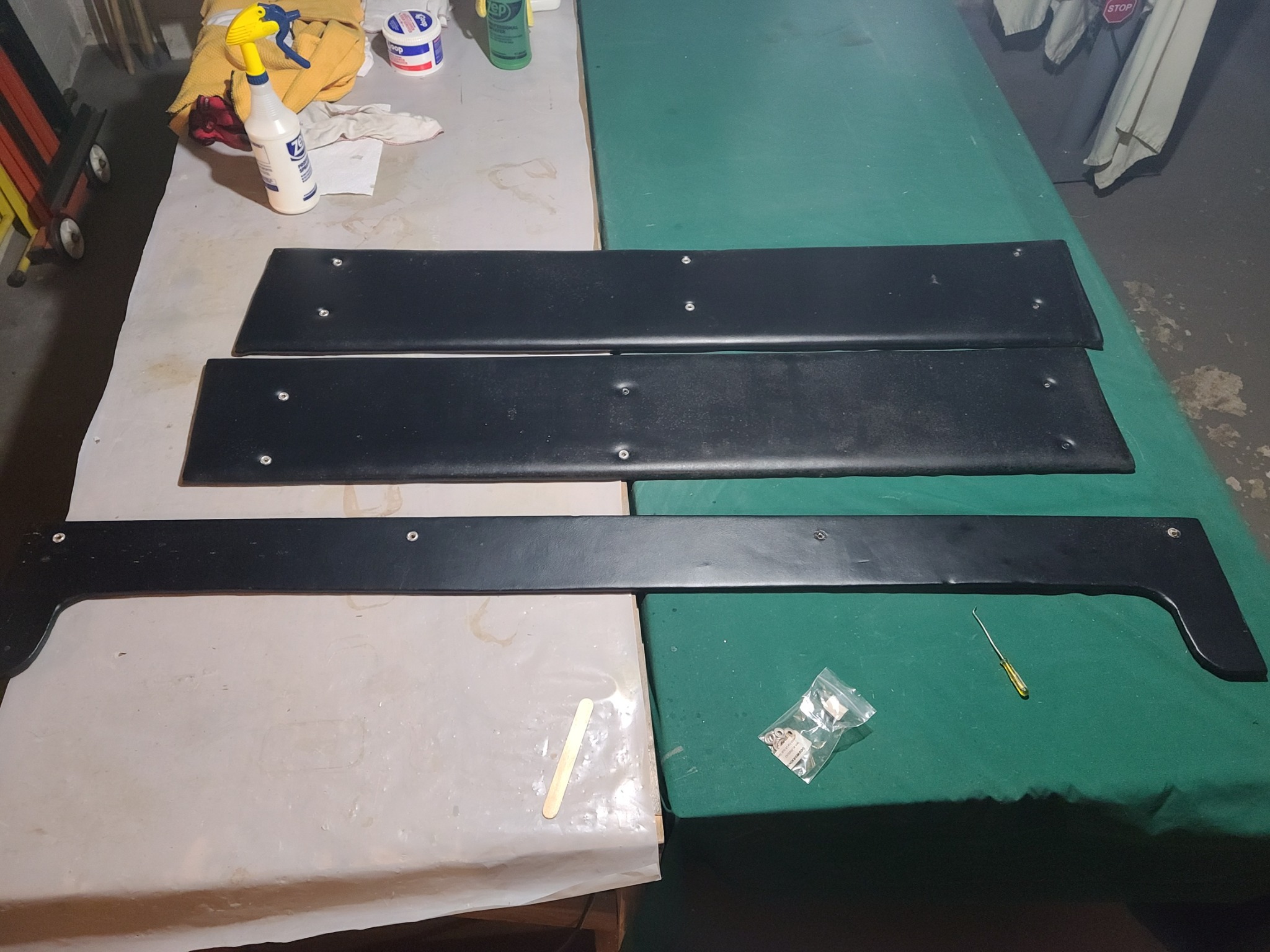
Ready to have the Naugahyde vinyl reapplied.


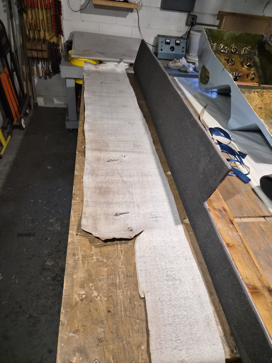
Laid the Naugahyde vinyl out with the original ski shelf attaching screws.
The screws provided a way to initially place the upholstery in the same position as originally installed.


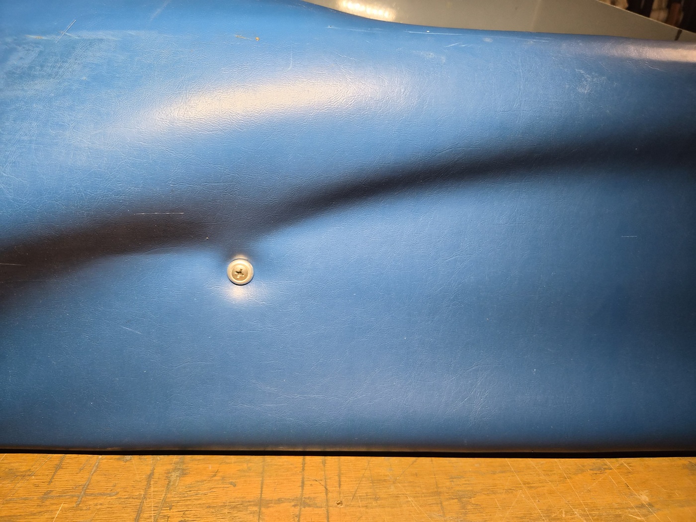
View of attachment screw used as a locator pin.


I then lined up the witness marks on the upholstery with their match on the wood and began stapling it all back in place. As a side note, I've found the polyester laminating resin used in the fiberglass layup remains a bit soft, allowing easy staple penetration. Once gelcoat is applied, the gelcoat proves to be must more brittle and difficult to staple through.


When originally installed, the upholstery was left roughly cut in place. Using a straight edge, clamps and a razor, I trimmed each edge straight.


It looks much cleaner!


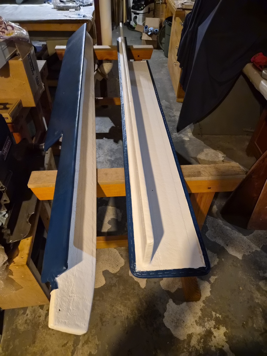
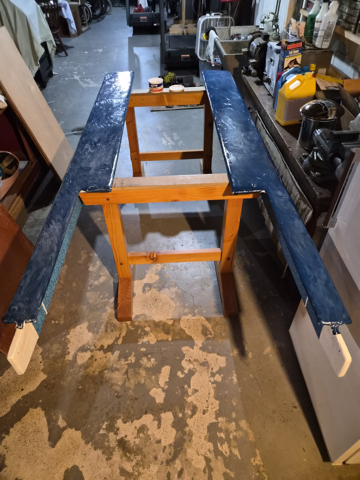
I masked up the upholstery with painters’ tape and applied two coats of gelcoat to the exposed portions of each ski shelf.


Phase one finished.

I'll complete the work in phase 2.

Please Log in or Create an account to join the conversation.

1971 Glasspar Newport Cruiser - Rejuvenation 2 months 3 weeks ago #149514

I get improving the mounting bracket but rebuilding a blower motor? You've taken re-engineering to a new level!

As for the upholstery, I'm guilty of going to extremes on prep work too. All stainless hardware everywhere, wood sanded/beveled/rounded to avoid sharp edges that lead to eventual worn sports.

Please Log in or Create an account to join the conversation.

1971 Glasspar Newport Cruiser - Rejuvenation 2 months 3 weeks ago #149516

  • Larsspar
  • Larsspar's Avatar Topic Author
  • Offline
  • Senior Boarder
  • Senior Boarder
  • Posts: 248
  • Karma: 5
  • Thank you received: 21
Hey Jim, as they say, a captain has to know his boat.
Are you sure you can rely on your engine compartment blower system? :laugh:

Finished up the Ski shelves. It was a lot of fiddly work. Admittedly I'm anxious to complete the interior work and move on to the work I enjoy most, which is the mechanicals and electrical. Really looking forward to emptying my basement.


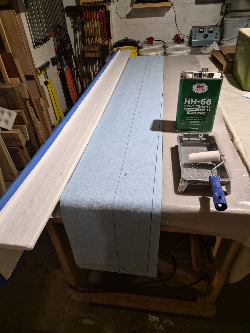
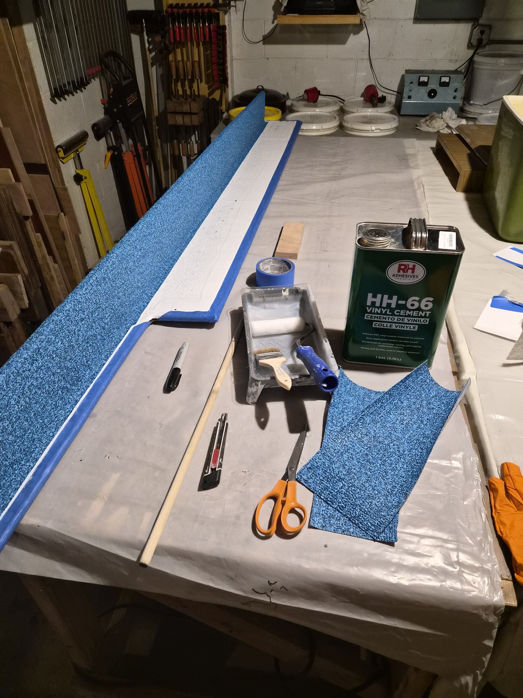
Pulled out scraps of vinyl flooring leftover from what I used to cover the floor and walls of the boat. I cut pieces to cover the portions of the ski shelf that's visible when sitting on the boat. Ordered a fresh gallon of HH-66 Vinyl Cement, set up my mini roller and had a chip brush nearby. I masked all recently attached Naugahyde with painter's tape and set off to work.


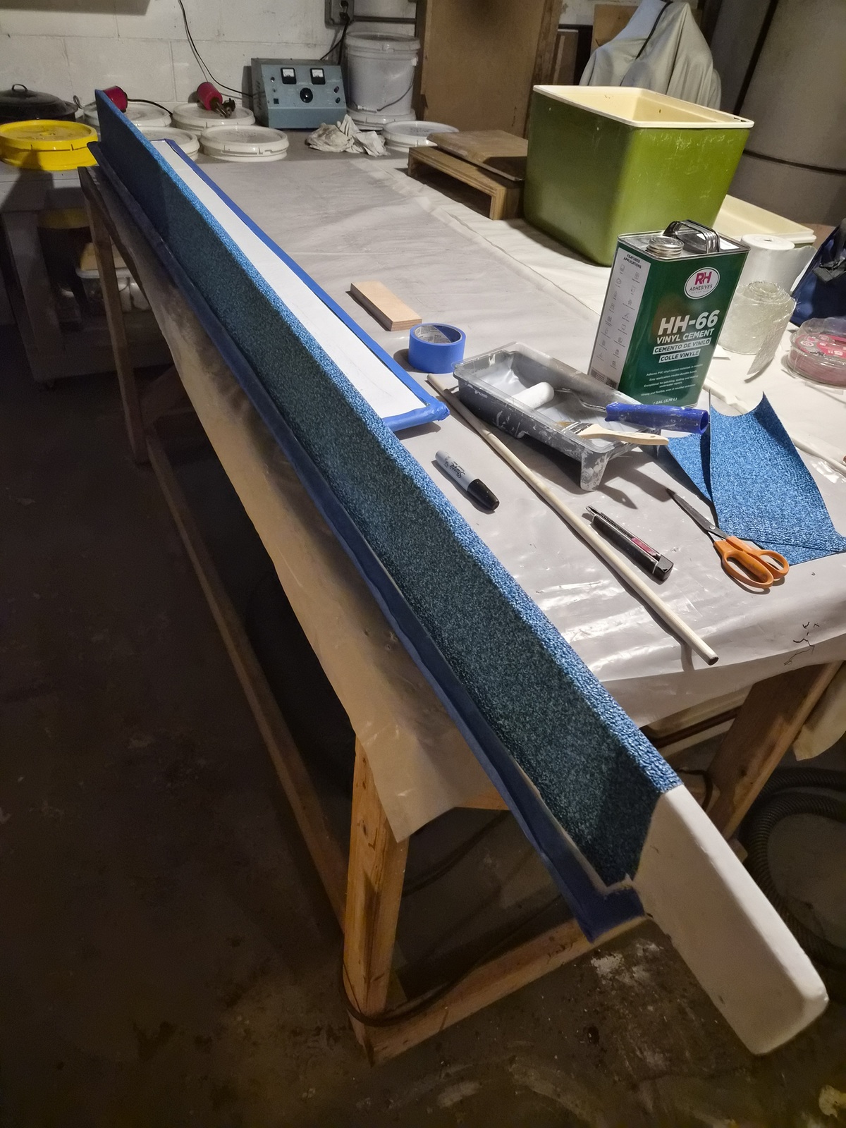
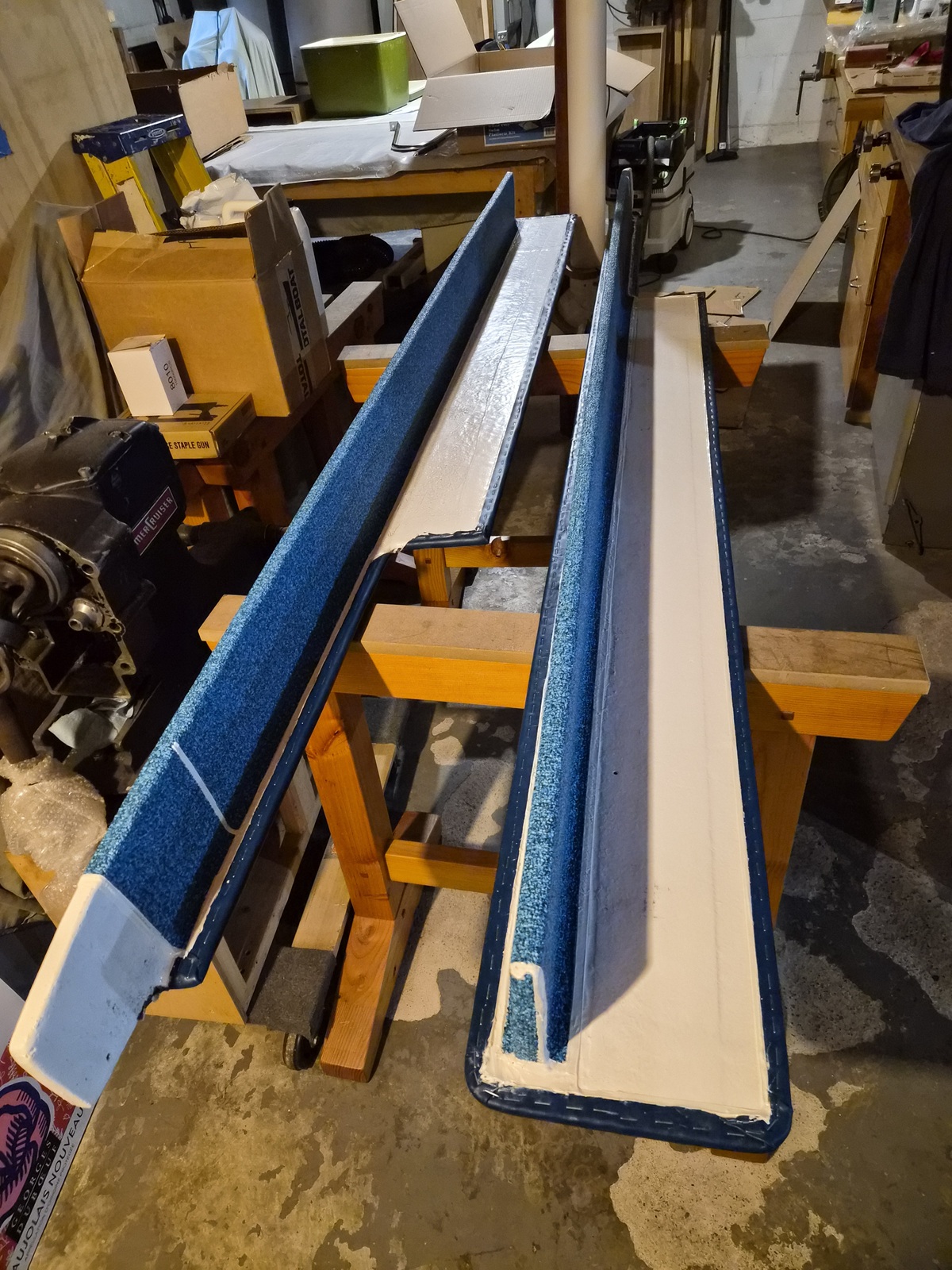
HH-66 works best as a contact cement, meaning you apply the glue to both surfaces, let the glue get tacky, then stick the surfaces together. I wrapped each shelf in two passes. First, I did the top side of each shelf and let it dry for an hour. I did so because the ski shelves taper as they make their way to the stern, which necessitated cutting reliefs in the vinyl on the underside which no one will see. This approach gave me a clean looking wrap when viewing the top side of the ski shelves.


View of the top side of one of the ski shelves.


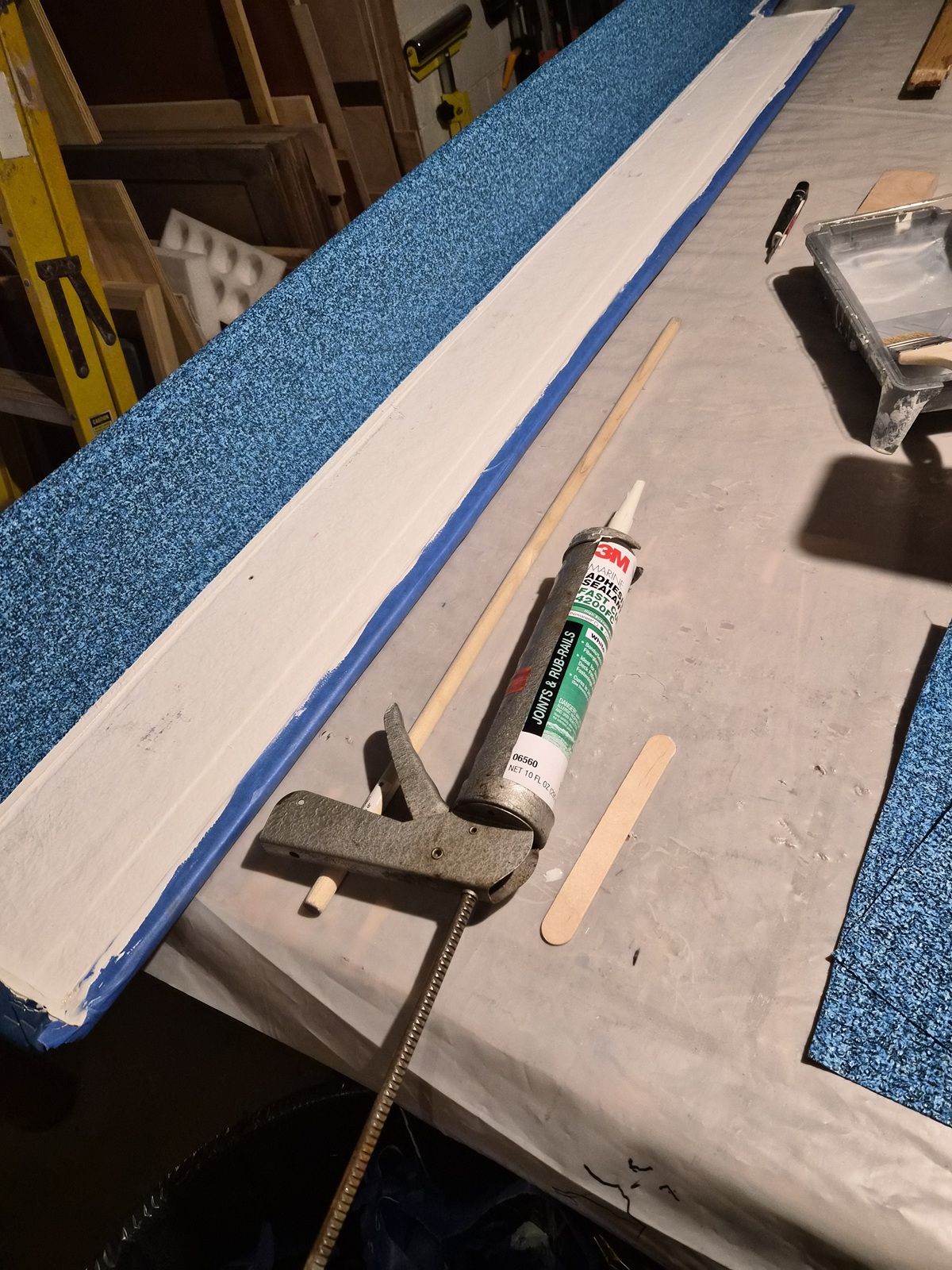
Next, I sealed all edges of the Naugahyde and vinyl flooring with 3M 4200. This keeps the edges of the material securely attached and keeps moisture out.


I also applied 4200 to the relief seems I had to cut on the bottoms and ends of each piece. I used ample painter's tape to frame all places I intended on applying 3M 4200 to leave me with clean caulk lines.

View after all painter's tape removed.


As with other interior pieces I massaged in a layer of Goop on the Naugahyde and let it sit for a couple hours. I then removed the Goop with clean cloths, applied a quick shot 50/50 mix of Simple Green and water to ensure all the Goop was all cleaned off and completed the process by applying a coat of 303 marine protectant.


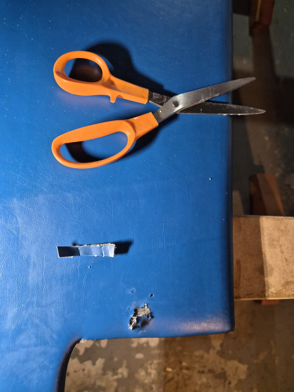
Last little detail. Both ski shelves had tear in the Naugahyde in the same spot where a mounting screw attaches to the hull near the fuel tanks. I trimmed some small pieces of Naugahyde and used HH-66 to tie the edges together and attached the Naugahyde to the foam. It didn't turn out very pretty but did strengthen the spot. Each spot will be covered by upholstery washers so much of the horror will be hidden.


Ready for installation and service.


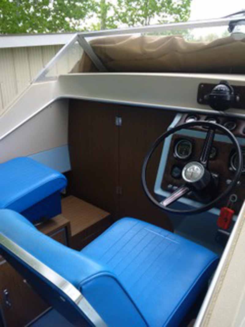
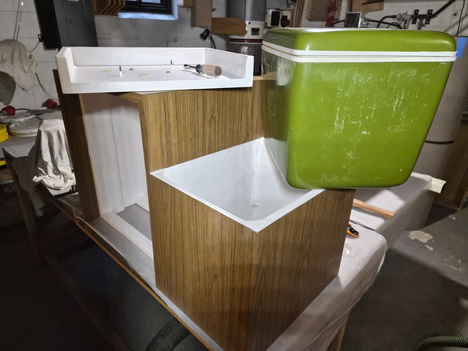
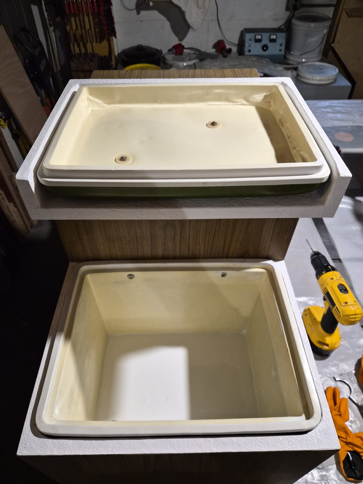
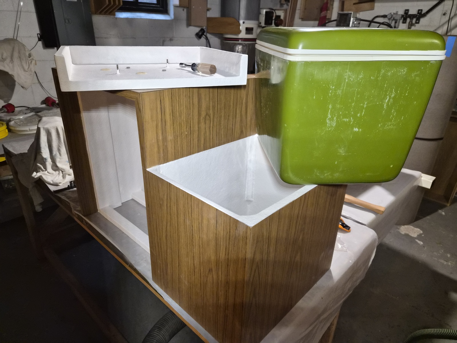
The Pilot's chair sits on a cabinet base which houses your classic pop-up camper ice box refrigerator and under the footrest sits what I believe is meant to be a dry storage container.


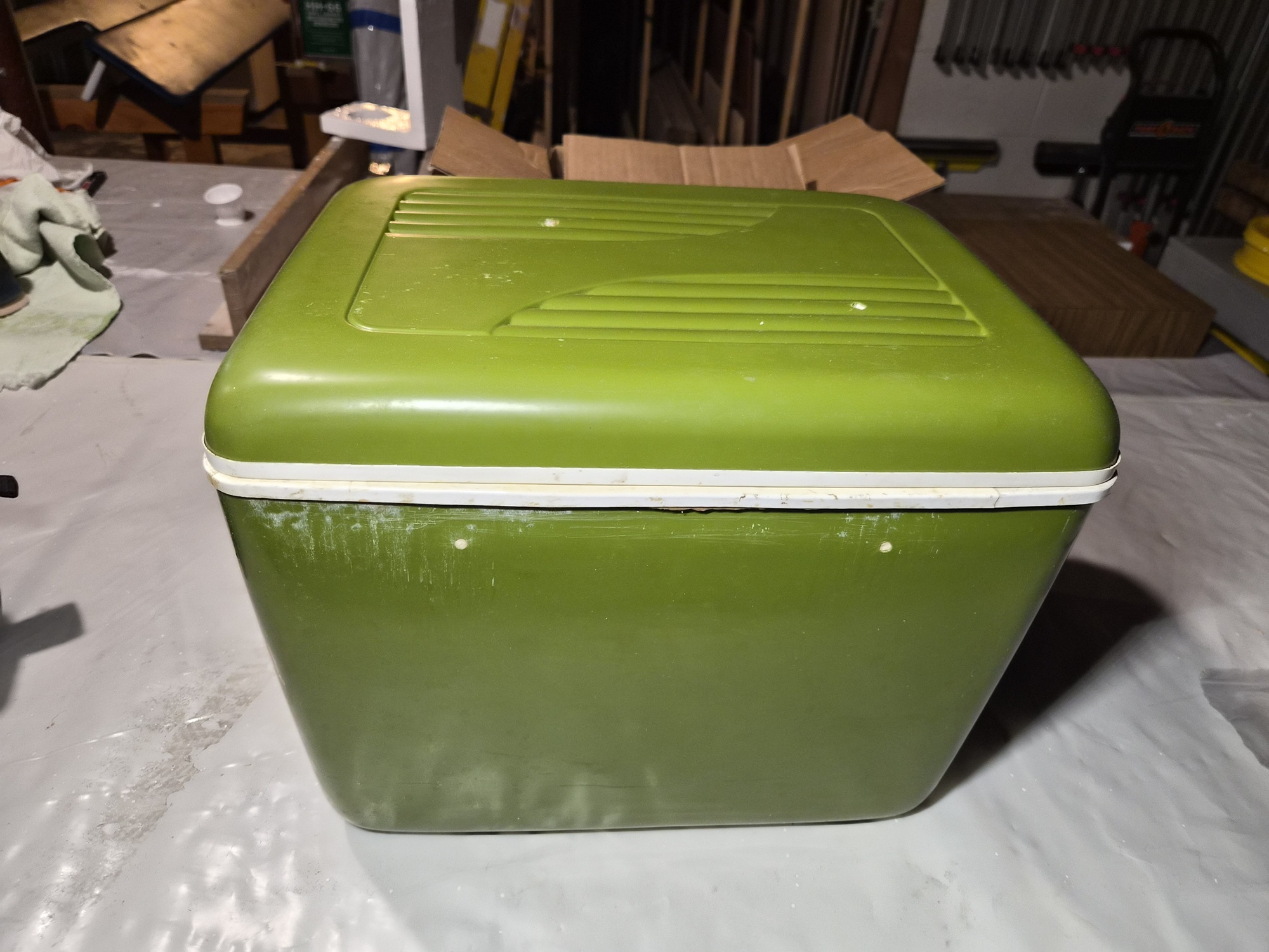
It looks like a classic cooler but contains no trademarks identifying manufacture. The lower portion was originally screwed through the sides of the container into the sides of the cabinet. The lid of the container is attached to the cabinet lid (upper right in the background) via two screws through its top.


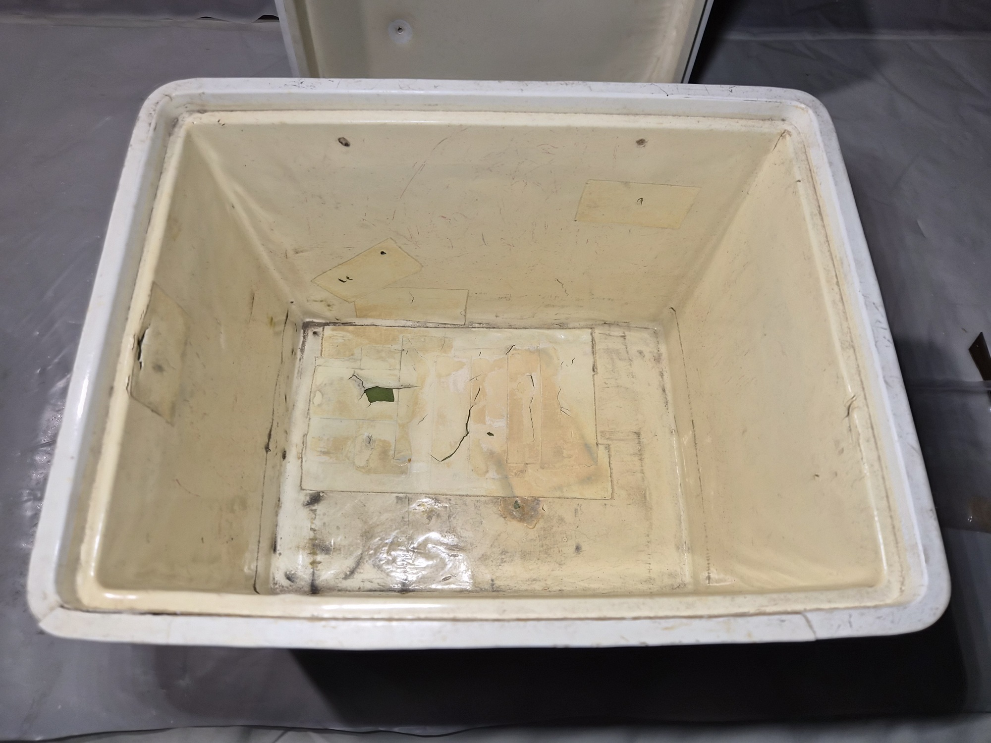
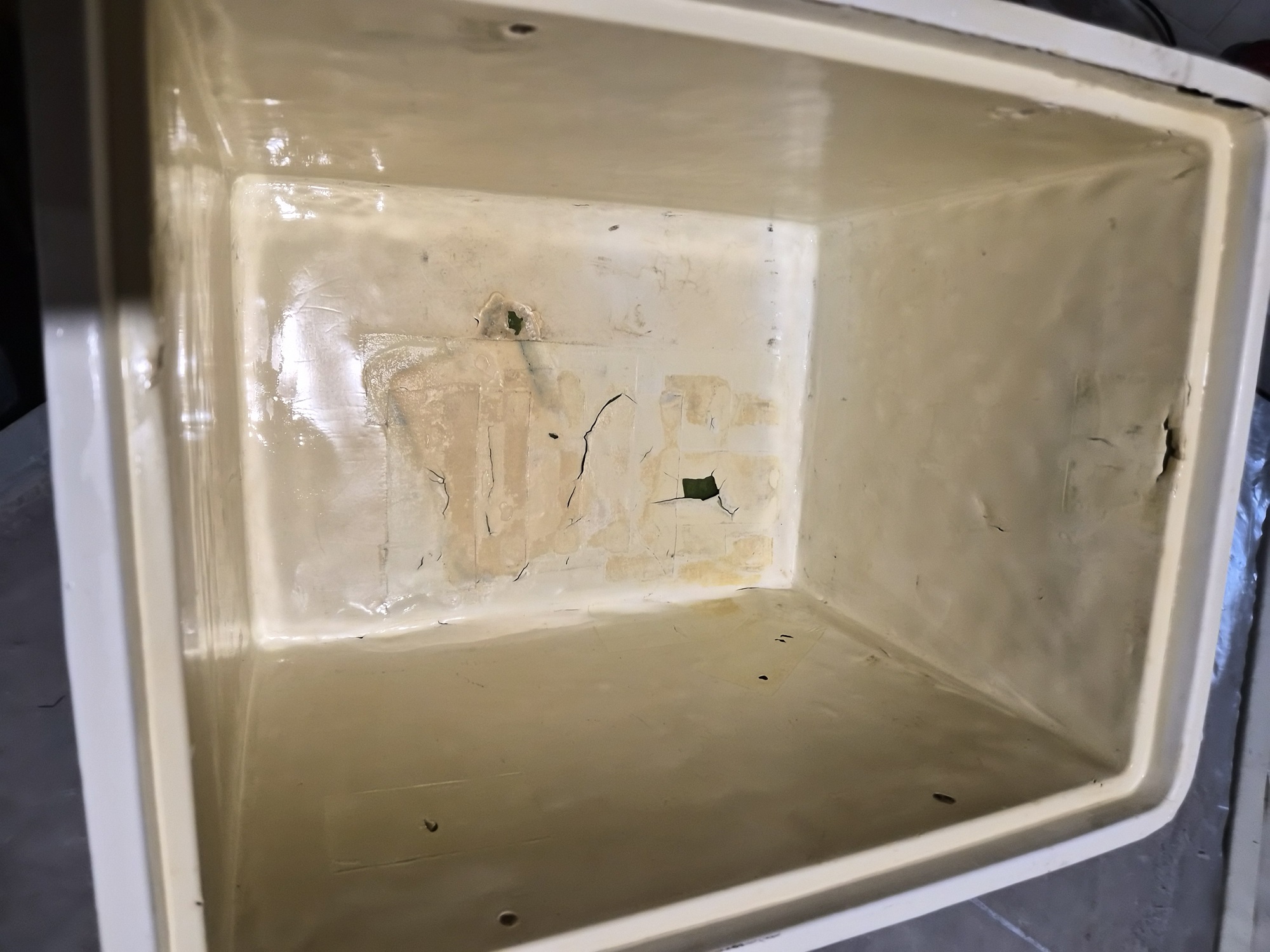
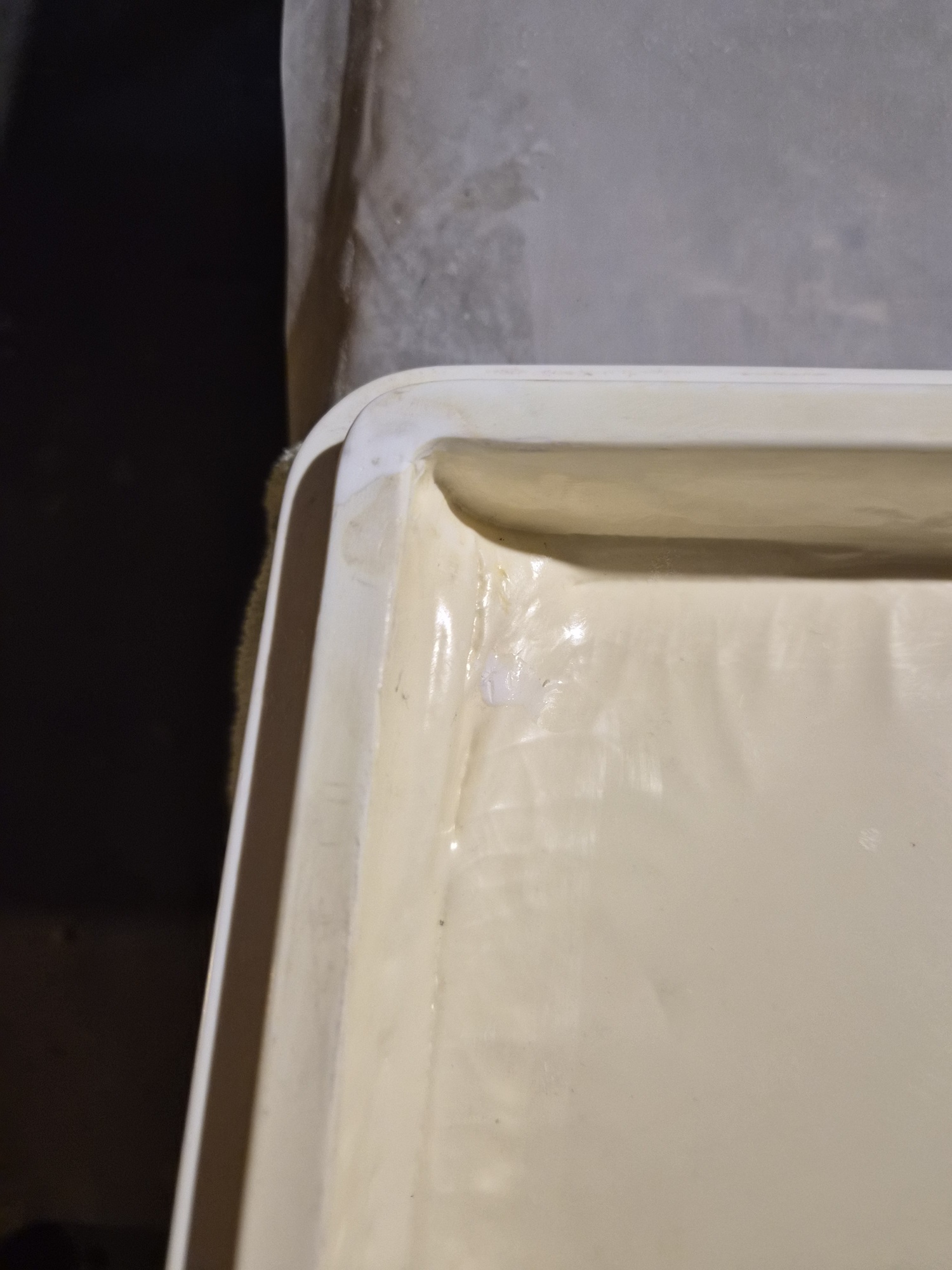
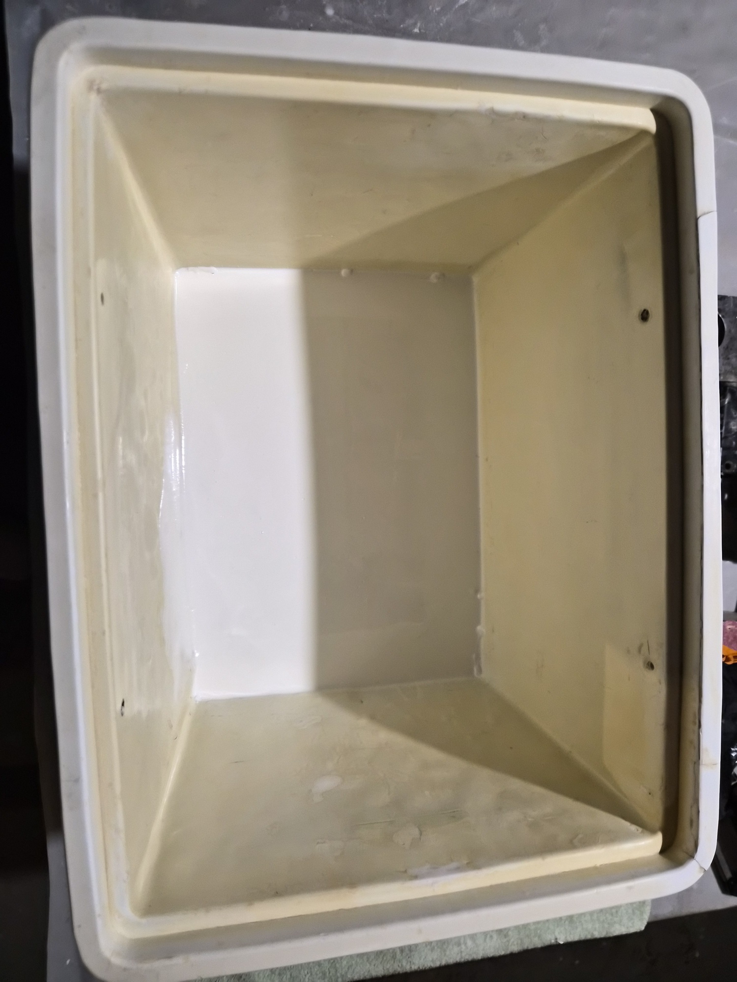
Well, unfortunately its lived a tortured life. I'm guessing a previous owner attempted to fill it with ice, or water got into it and it froze over winter. Regardless, it was full of holes and looked grim. In this case, I did 'not' set out to re-engineer the boating industry. I spent hours looking at used coolers but found nothing that remotely looked like it, or had the same dimensions. I had to figure out how to repair it.


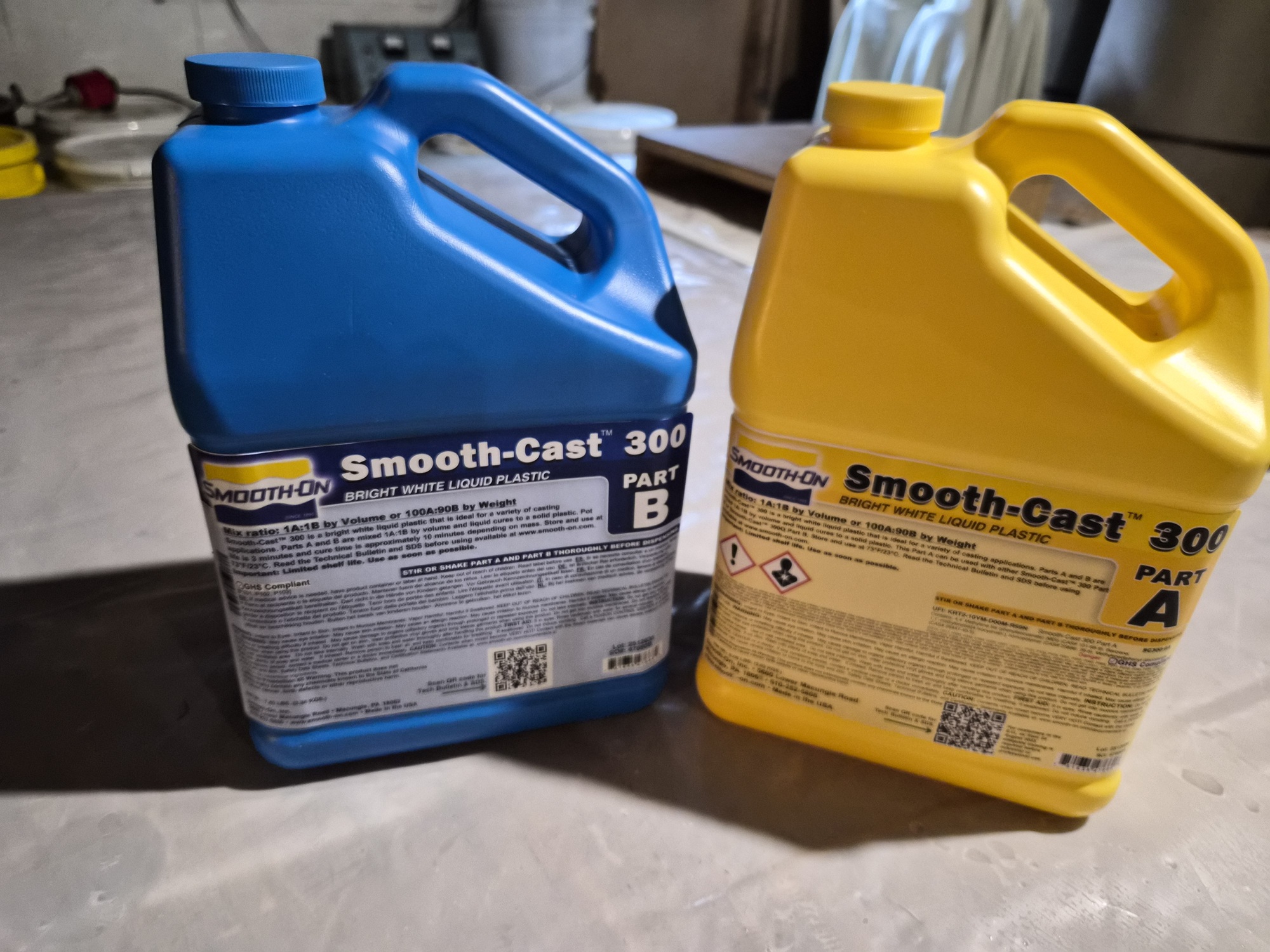
After doing some research on liquid plastics and watching some videos, I decided to try Smooth-Cast 300. It's a two-part polyurethane that as it cures turns bright white. DISCLAIMER: Its designed purpose is to create casts from molds, as opposed to repairing a cooler. IT'S ALSO NOT CLEAR TO ME IF IT'S FOOD SAFE.


I started by giving the container a good scrubbing with a scotch bright green pad, vinegar and baking soda. This process really cleaned it up and clearly left the identifiable areas requiring attention.
I ended up buying the Smooth-Cast 300-gallon kit because as you can see, I had a lot of work ahead.


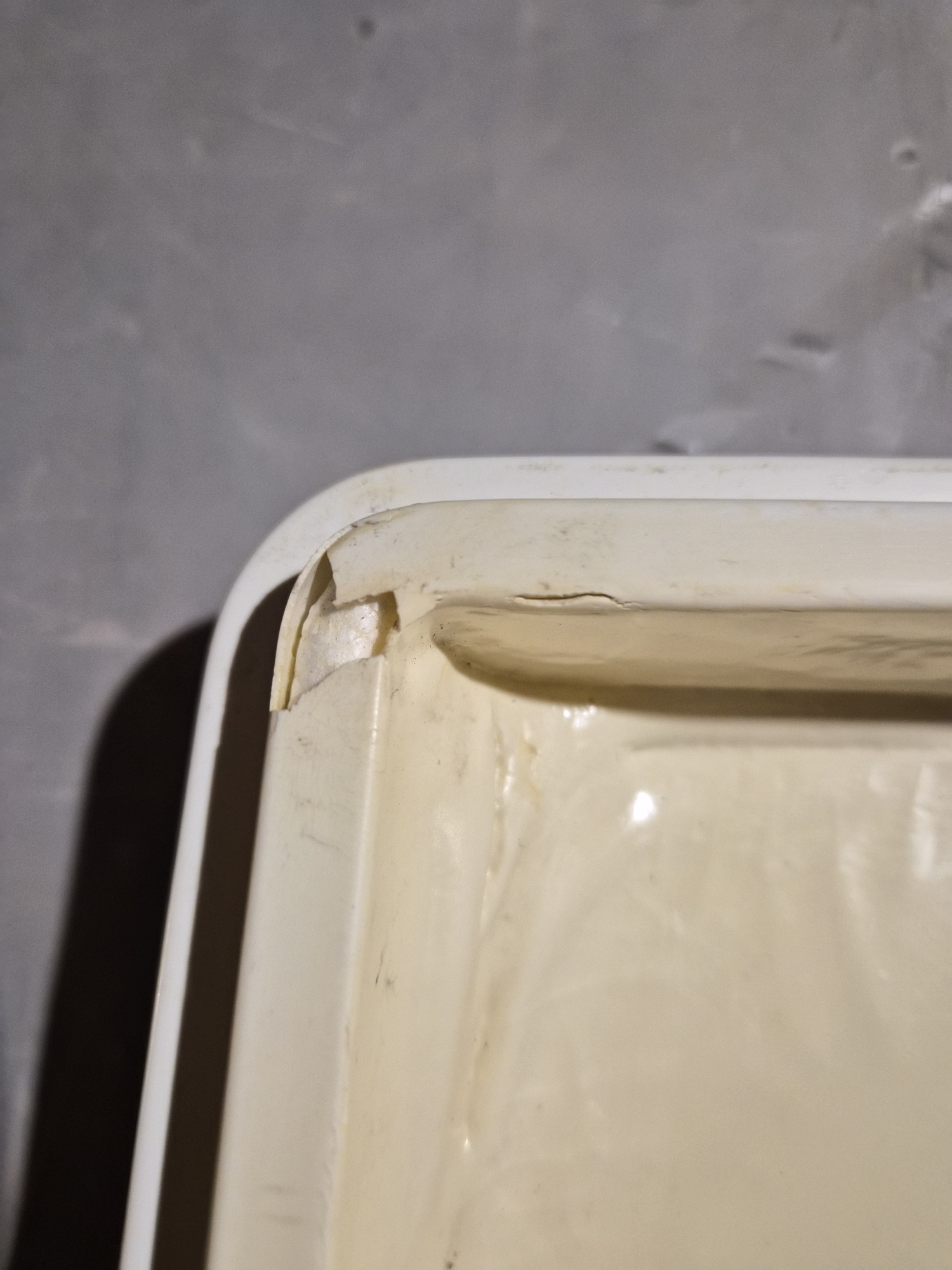
I started with a small gap in the lid.


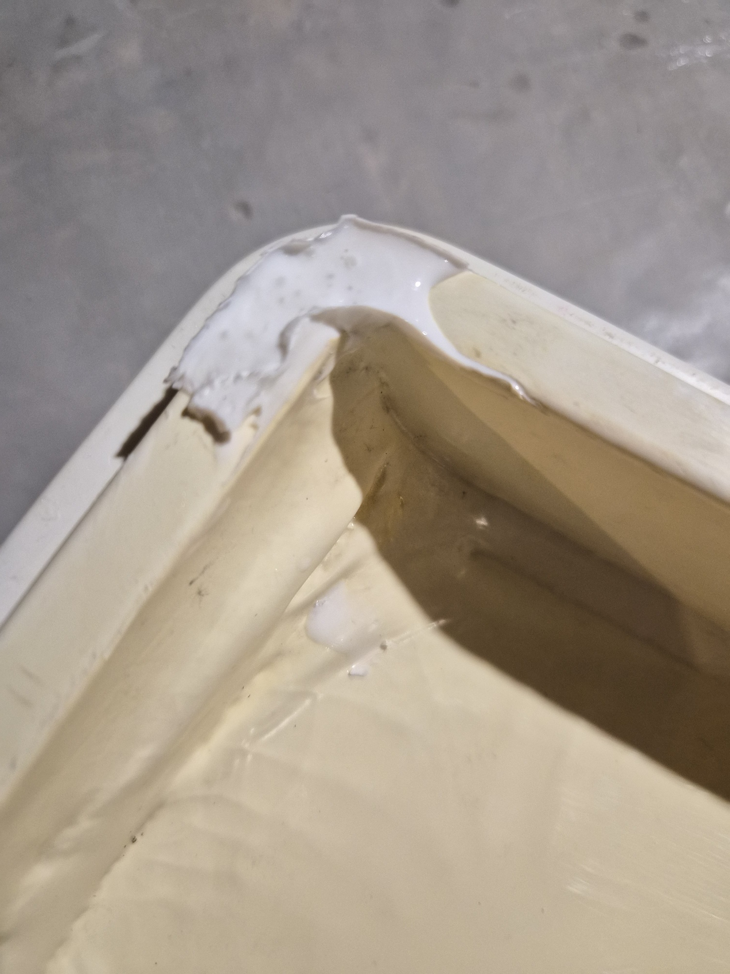
I mixed a small batch 50/50 as instructed and poured it into the fracture. I had placed packing tape of both sides to form a small dam. Each batch has a three-minute working time window and starts out as a fairly viscous clear liquid. As it cures, it starts to get warm, thickens up and turns white within four to five minutes.


I let it sit for an hour then came back with sandpaper, first 100 grit to remove most unwanted material, the 200 grit to leave a smooth finish. After twenty-four hours the patch was very solid and fairly inconspicuous.


Each wall was done one at a time using small batches to fill the cracks, craters, and imperfections.
The floor had some much larger damage, so I decided I wanted to completely cover it in a thin layer of the product. I had to turn to math to figure out the correct amount to mix. I pulled out a tape measure and determined the floor of the container was 13.75 inches long and 9.75 inches wide equaling 134 square inches. Knowing the solution would leak into the crevasses, I decided I want a .25-inch-thick pour, which equals a total of 33.5 cubic inches. (9.75 x 13.75 x .25) Converting cubic inches to ounces (1 cubic inch = 0.554113 fluid ounces) so 33.5 cubic inches x 0.554113 = 18.57 fluid ounces. I rounded my pour up to twenty ounces.

The results turned out well!

I have a couple bumps left to sand, but the majority of the imperfections have been repaired. Time will tell how well the patches hold up. I intend on using the container for dry storage only.

Please Log in or Create an account to join the conversation.

1971 Glasspar Newport Cruiser - Rejuvenation 2 months 3 weeks ago #149517

Amazing, never heard of the stuff.
But will it ever see the lake before it's obsolete?
What am I asking, it was obsolete when you bought it.

Please Log in or Create an account to join the conversation.

1971 Glasspar Newport Cruiser - Rejuvenation 2 months 1 week ago #149530

  • Larsspar
  • Larsspar's Avatar Topic Author
  • Offline
  • Senior Boarder
  • Senior Boarder
  • Posts: 248
  • Karma: 5
  • Thank you received: 21
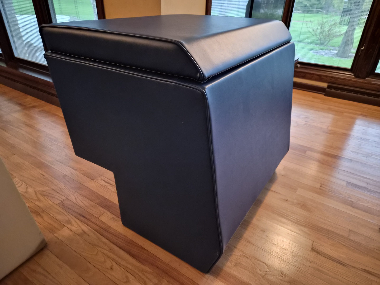
Finally had the chance to complete my engine cover. Unfortunately, my upholstery partner who had original matching Naugahyde to my boat, didn't turn out to be one of the better vendors I've worked with on this project. The shop appears to move a lot of business, but organization is not their strong suit. Very nice people, but required weekly calls to get the project completed, lost my pictures/instructions, lost my original upholstery meant for use as templates, lost the leftover upholstery I needed to match the rear seat bases to the engine cover, put a liner inside the lid which I had to remove so I could install insulation. They didn't correctly remember what I wanted done with my cabin cushions; a future post on this, but the original to the boat cushions were nearly destroyed.


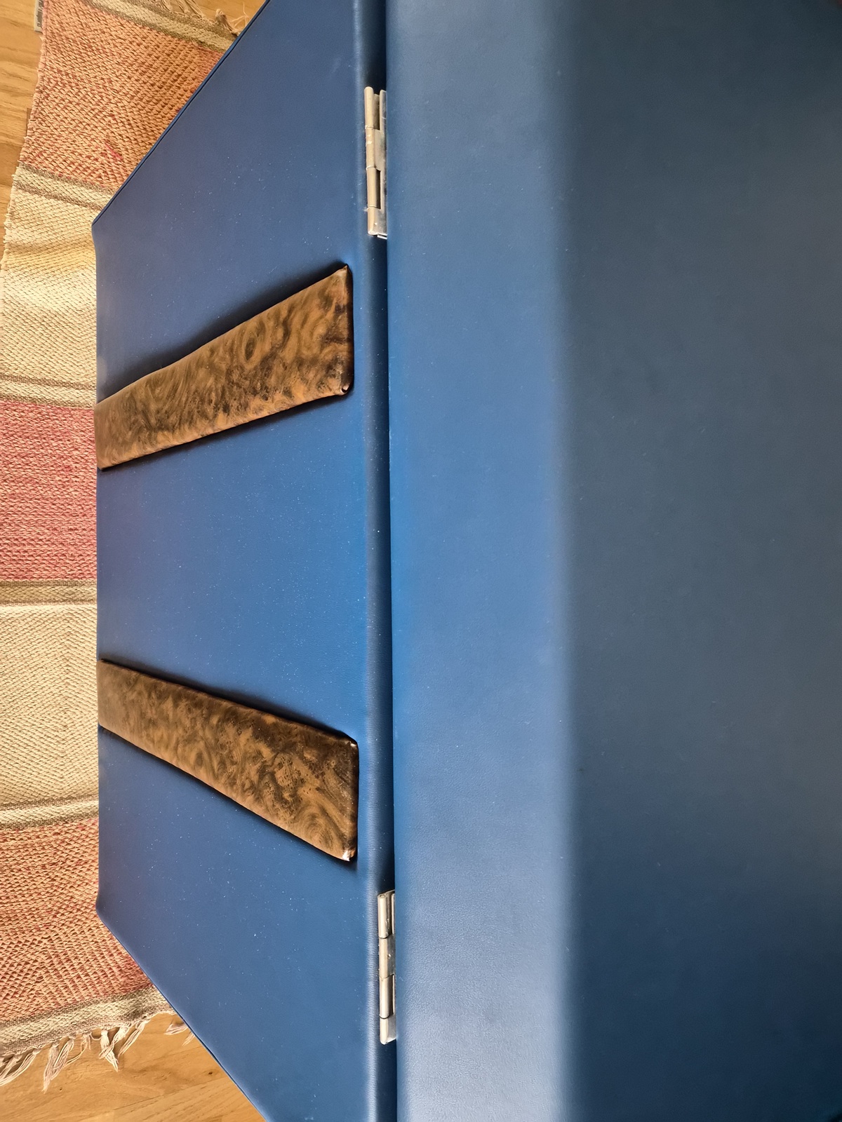
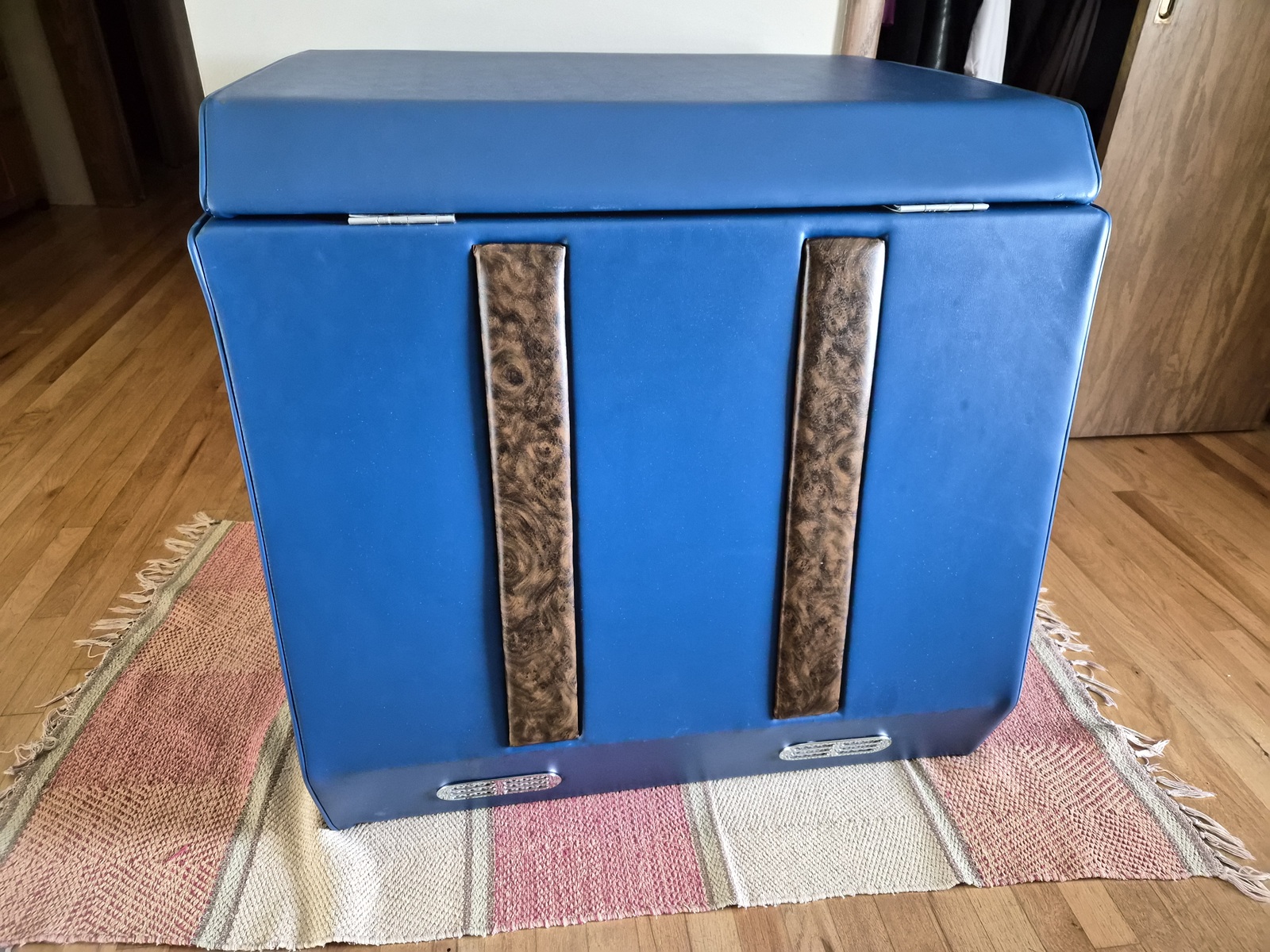
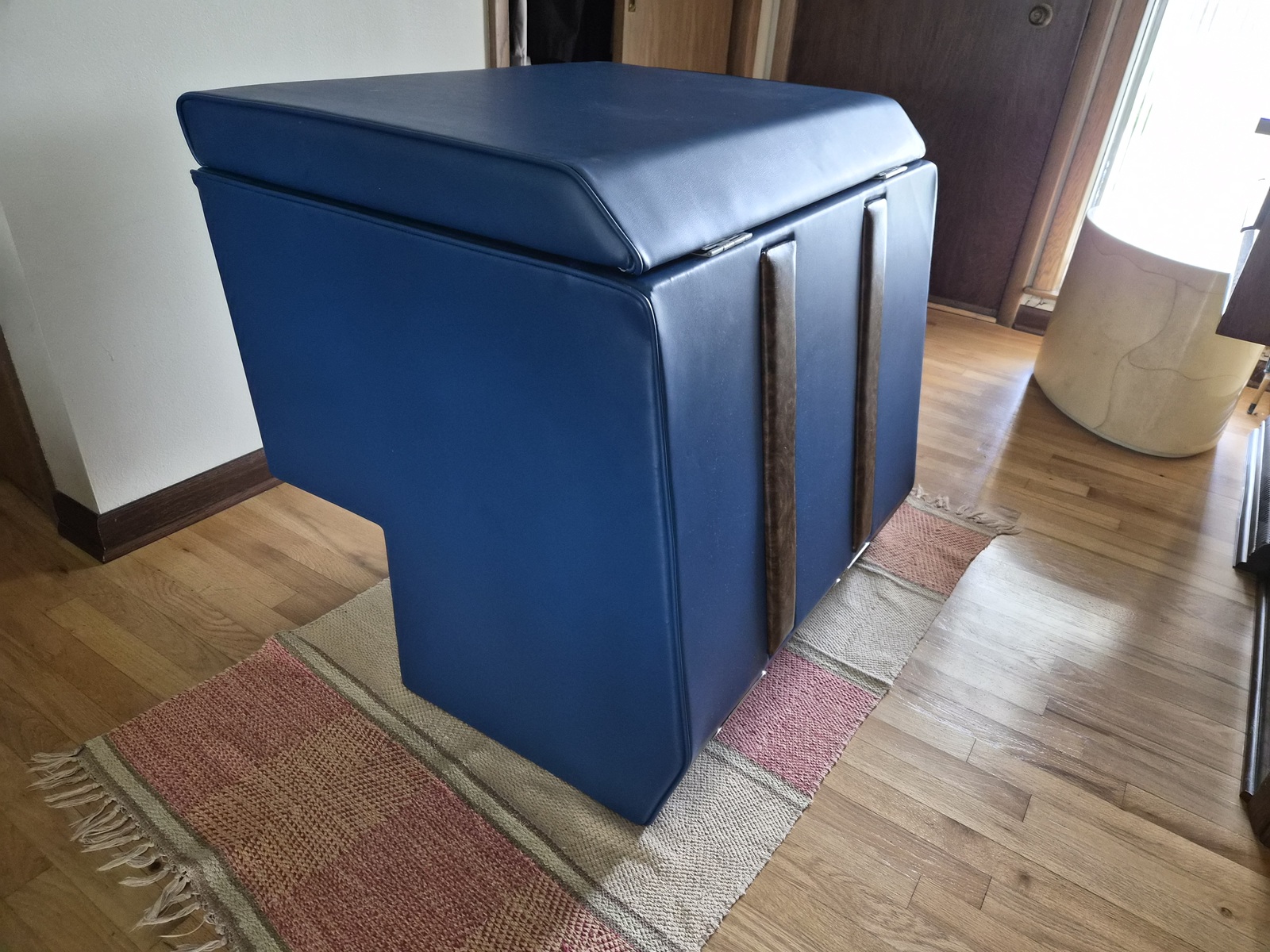
This is what I brought home. The lid is laying on the lower portion or base of the engine cover. Looks pretty nice.


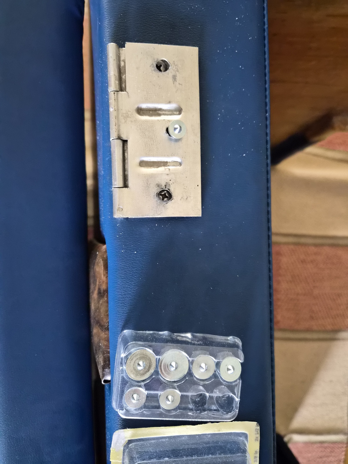
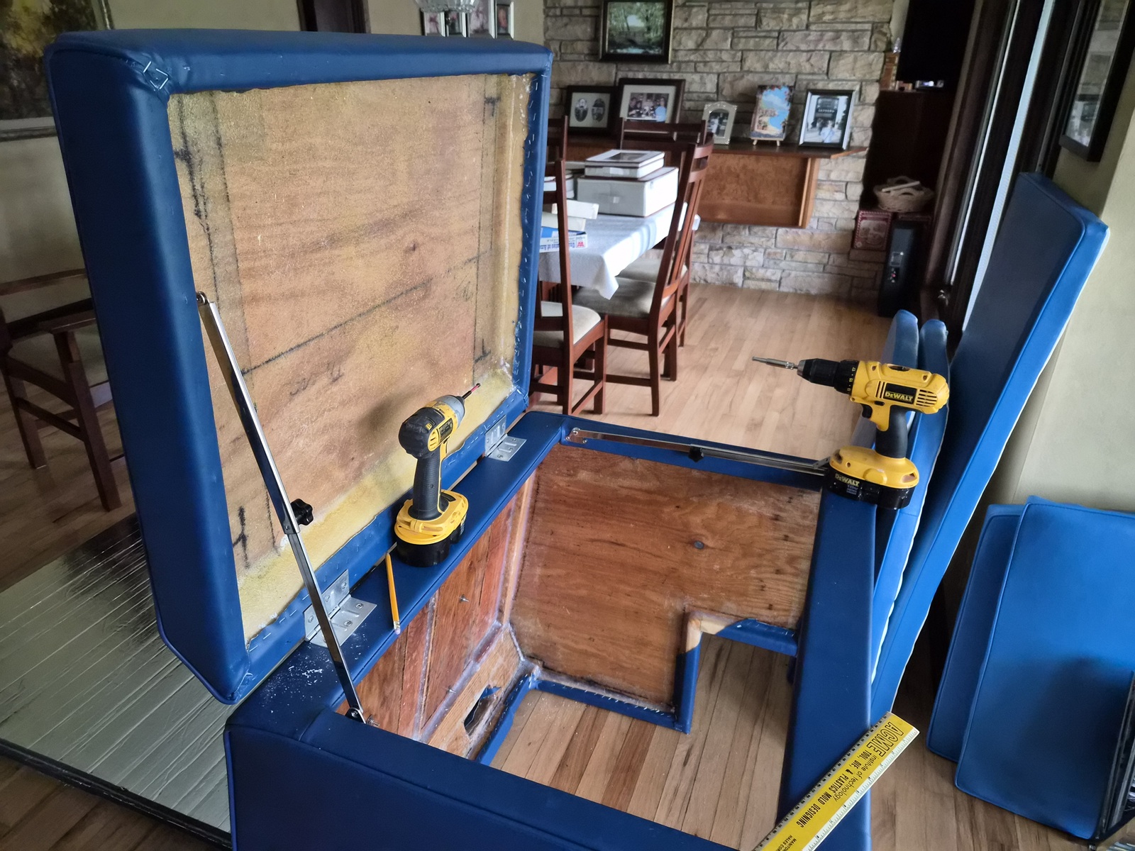
The first thing I had to do was install the hinges attaching the lid to the base. Using some measurements to ensure the components uniformly aligned, I was easily able to attach the hinges to the base. The harder but was aligning and marking the lid. From previous woodworking projects, I have these dowel center pin sets, two of which fit the hinge holes perfectly. I was then able to carefully lay the lid on top the pin sets and press down, leaving me perfectly aligned marks to drill screw pilot holes.


Well, leave it to me to mess it up. The drill walked back on me when I was drilling the starboard side pilot hole. Once installed, that side of the lid clearly sat a 1/8th inch further back. I unscrewed the lid, filled the starboard side holes with epoxy dispensed out of a glue syringe, let it dry and then drilled the holes in the correct place, the second time.


Beauty shots with vent grills and simulated burl elm inserts installed.


I think it looks pretty nice!


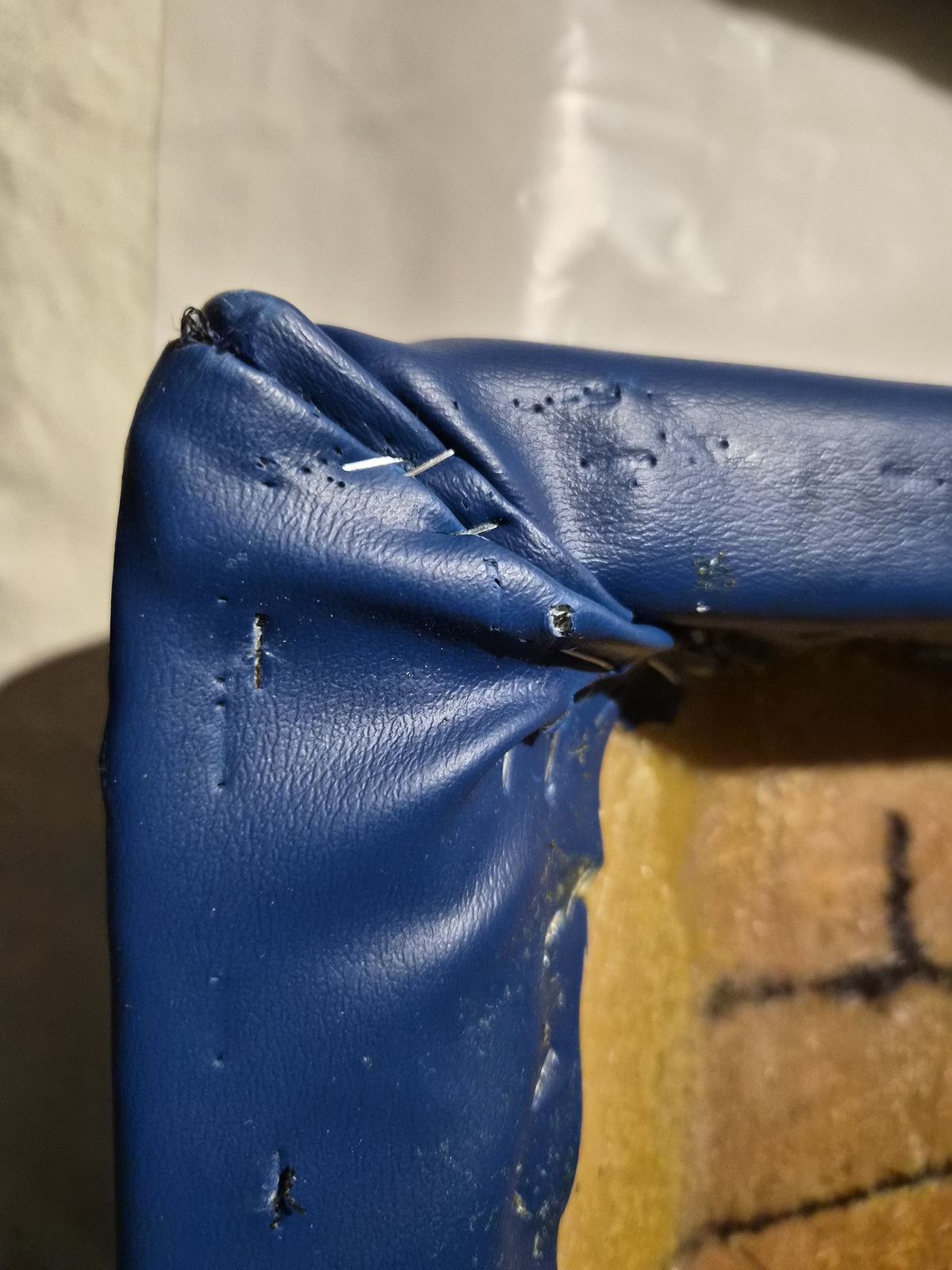
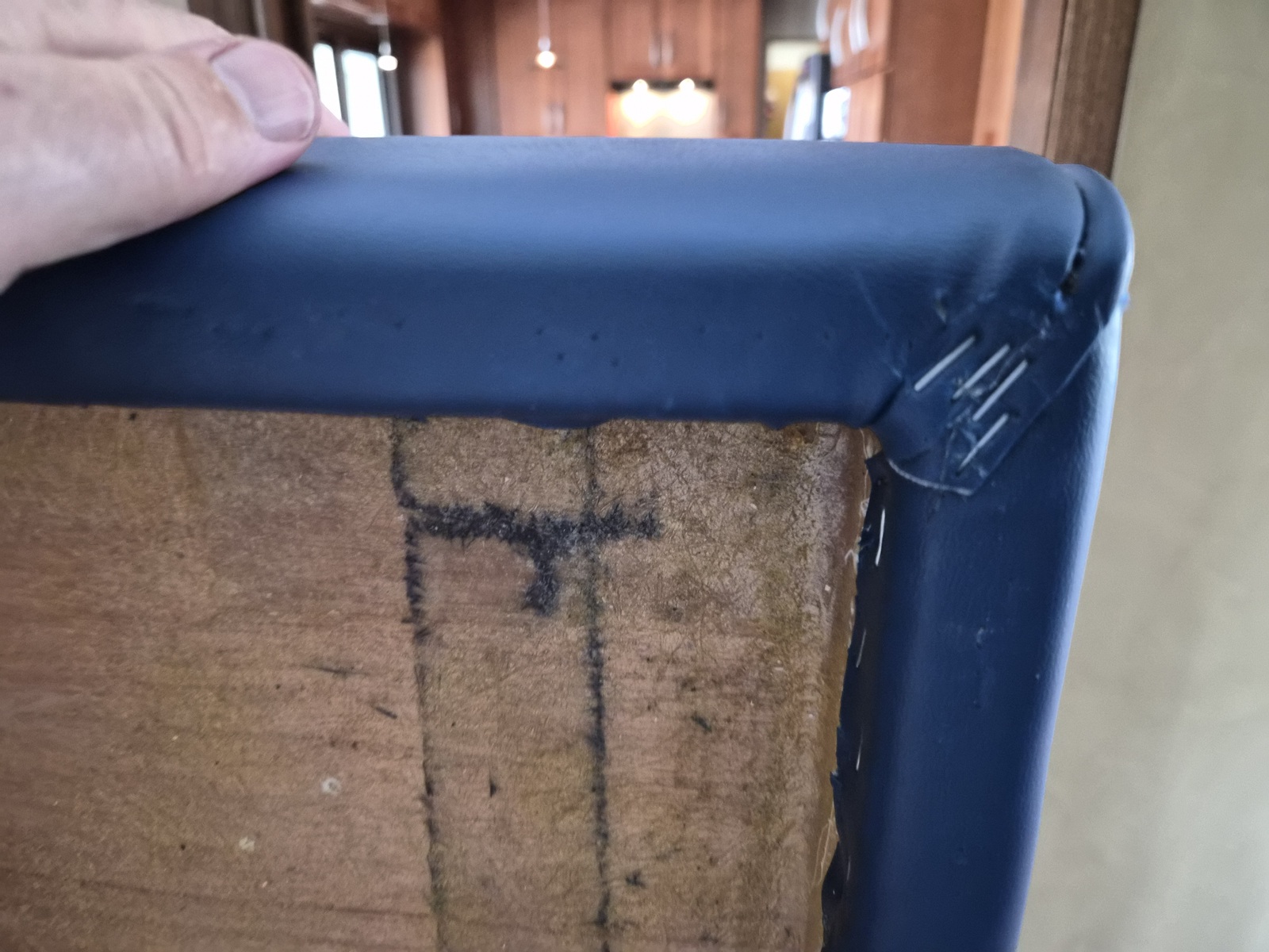
An example of my disappointment. I believe my project was carried out by one of the lesser experienced members of the shop. This is one of the lid corners. There is so much upholstery folded over, the lid doesn't lay flush, rather a 1/4" gap is created. You can also see the remnants of the two hundred staple marks put into the new fabric where a liner was attached, which I removed so I can install insulation.


I pulled all the staples out, carefully trimmed the excess upholstery and reattached it, leaving a much more uniform finish. I did this to seven other points where the lid and base meet. I left the other corners of the base alone. I just don't have the time to correct them currently.


Purchased a pair of SeaLux Marine Premium 316 SS Hatch Lid Stays and installed them. These are nicely finished parts, but I was unhappy with the riveted hinge points. I drilled the rivets out and installed 10-24 stainless screws and nylon nuts. This setup will be more robust and also helped me during lid insulation installation.


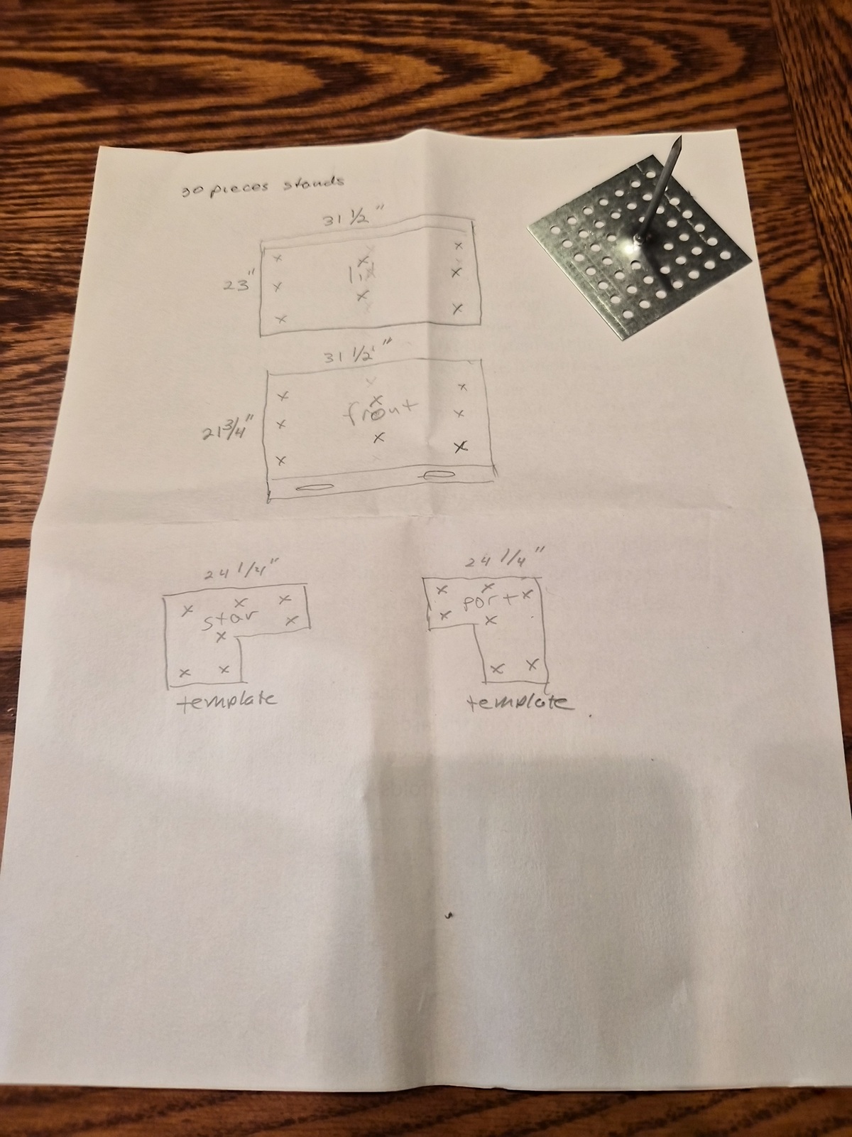
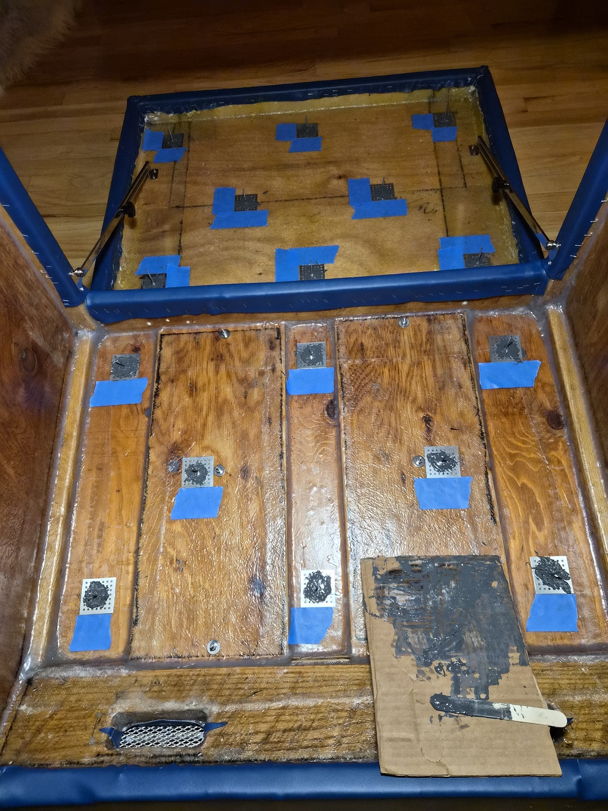
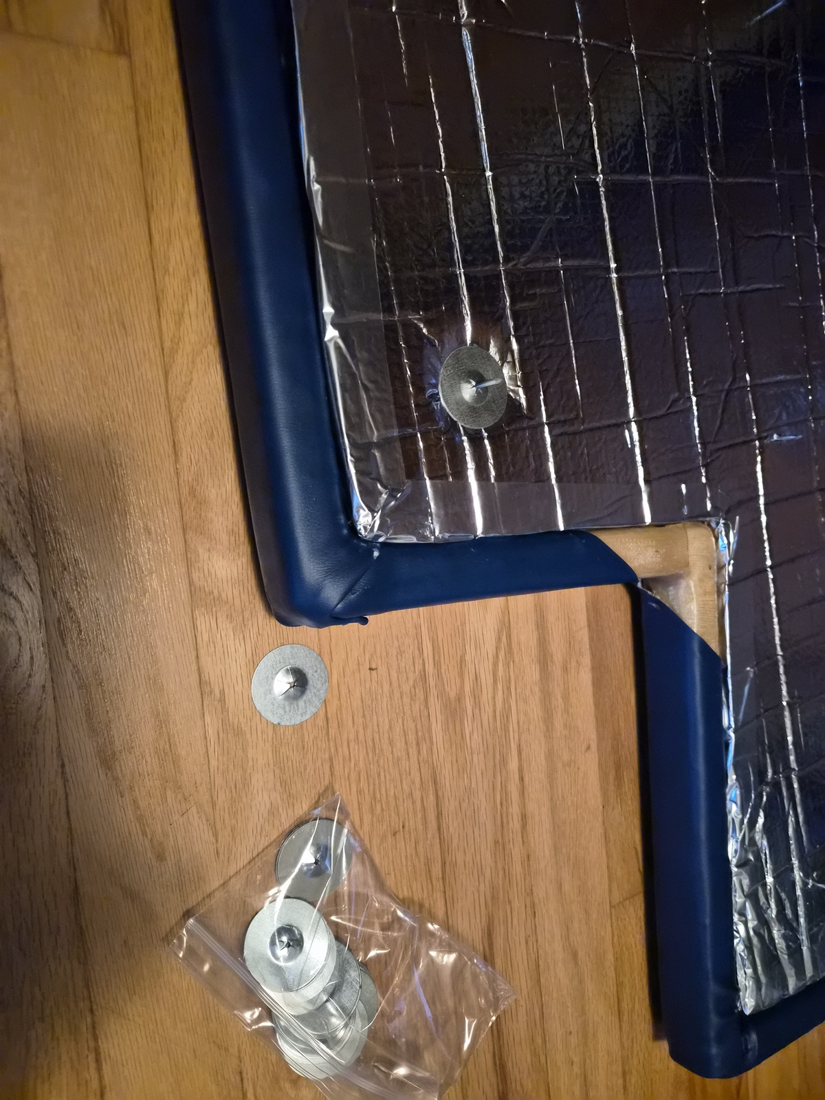
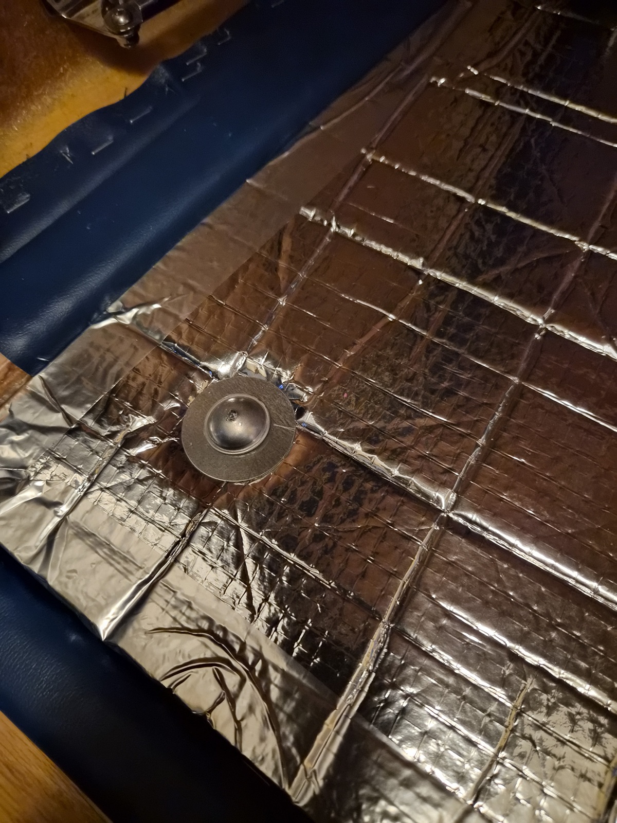
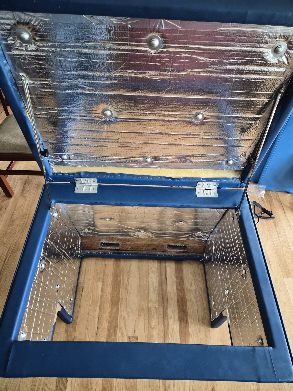
I studied and wavered around a while on what insulation to install inside the engine cover. I ended up 'investing' in West Marine Acoustical Foam Model # 216866 Mfg # 47501. It's one inch thick, multi-layered, insulation which has a foil face and an adhesive back. Spendy stuff, I needed two kits and also purchased an extra anchor set. The installation instructions suggest installing insulation anchors on all vertically facing surfaces. This is one of the anchors included in the kit.

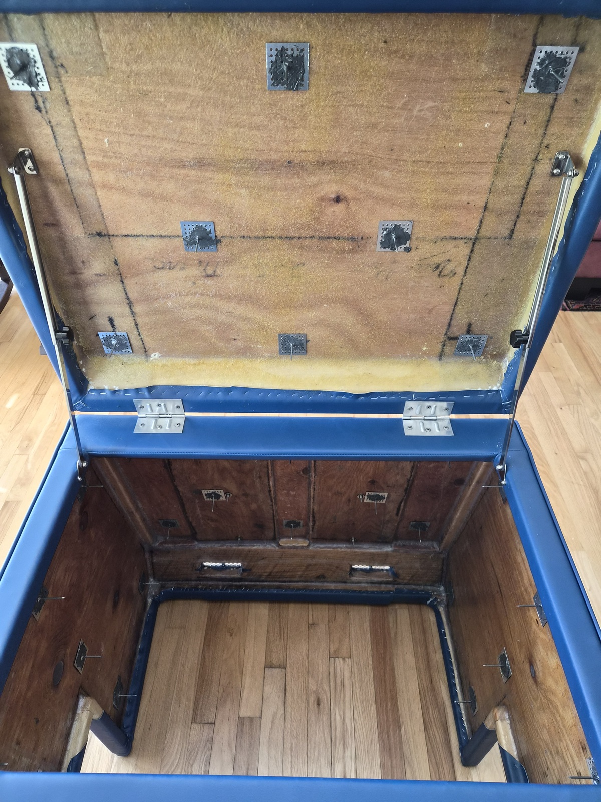
As part of my continued desire to re-engineer the boat industry, I decided I was going to use the anchors on all four engine cover surfaces requiring insulation. No insulation is going to de-laminate on my watch. I have thirty anchors total to work with and took the time to lay out and map them prior to installation.


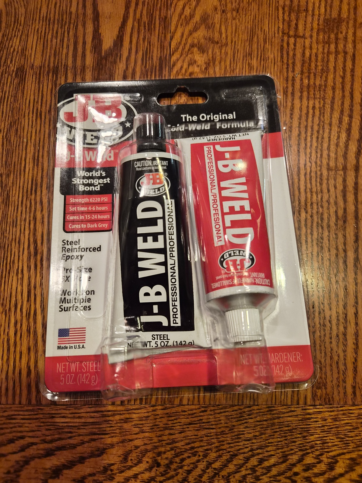
I acquired the 'professional' size JB Weld 10oz pack.


The anchors were glued to the engine cover using JB Weld in three waves over the course of three days. I placed painters' tape down ahead of time to aid alignment of each anchor during the heat of glue up battle.


Once all the anchors were installed, the engine cover remotely resembled an 'Iron Maiden'.


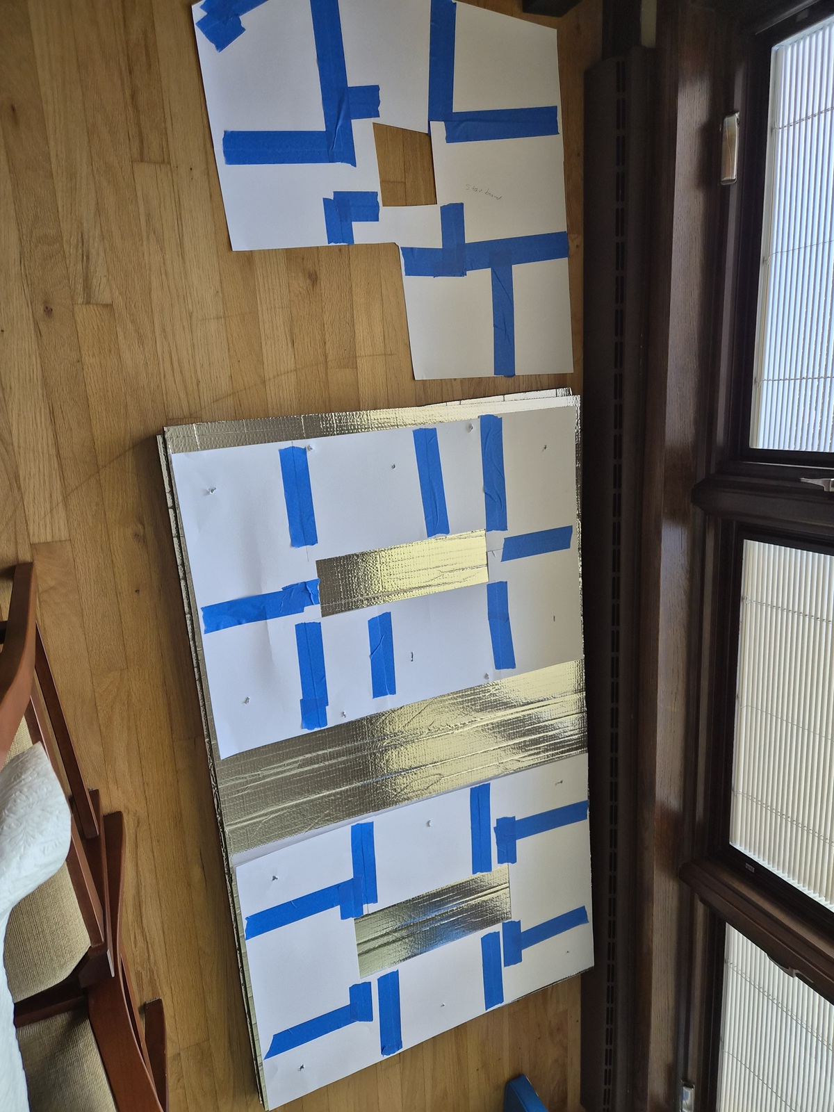
Using card stock, I created a template of each of the four surfaces I wanted to insulate.


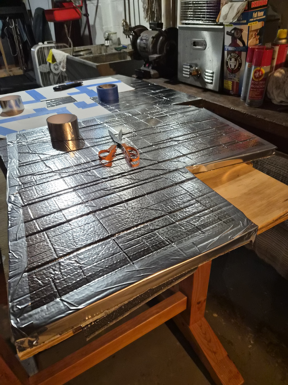
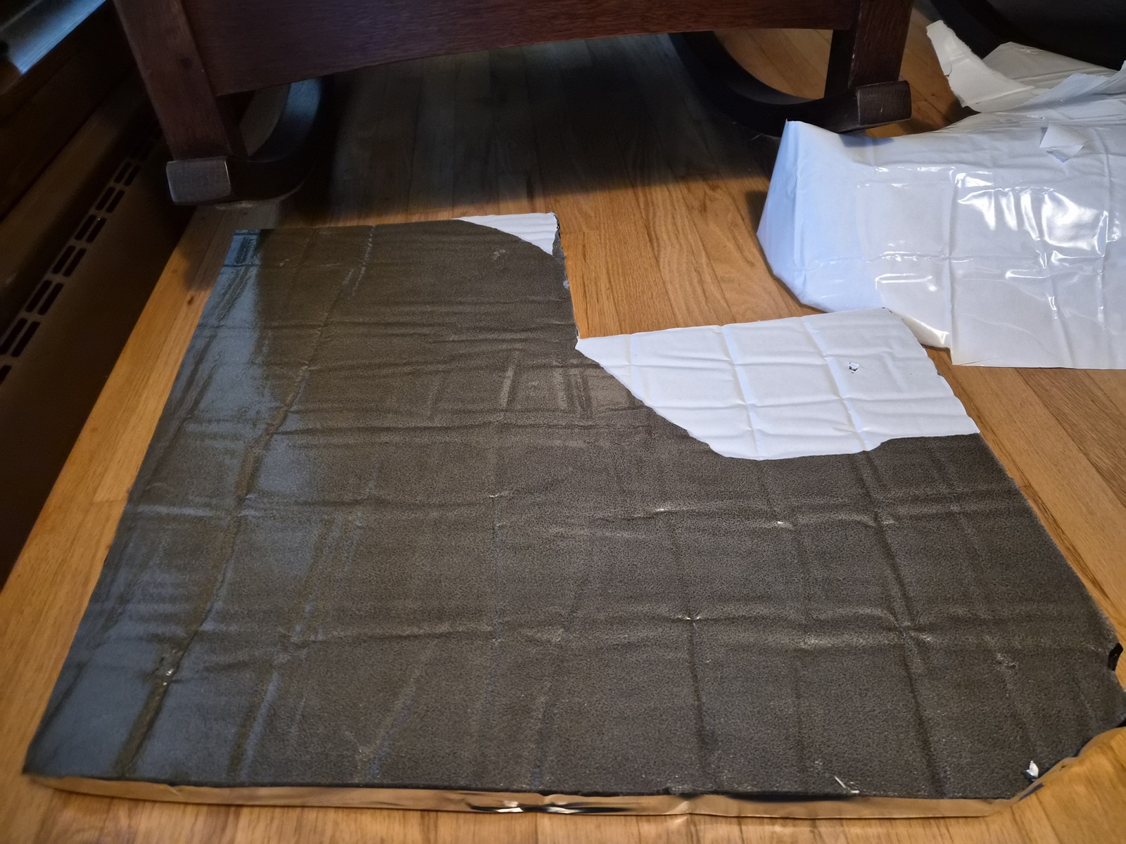
With the foil side up, I taped my templates to the insulation and used a long straight razor utility knife to cut the insulation. Each cut took four or five passes of increased depth to get clean results. The adhesive layer on the bottom is rigid and requires a bit more pressure to be trimmed. The kit includes foil seam tape, which I used to seal the ends of each piece.


I test fit each piece prior to final installation. If you look closely, you can see the anchor nail holes left from the test fit. I then removed the white backing plastic exposing the adhesive layer and proceeded to complete final installation.


Once positioned and stuck in place, I installed the included insulation hold down washers onto each anchor pin.


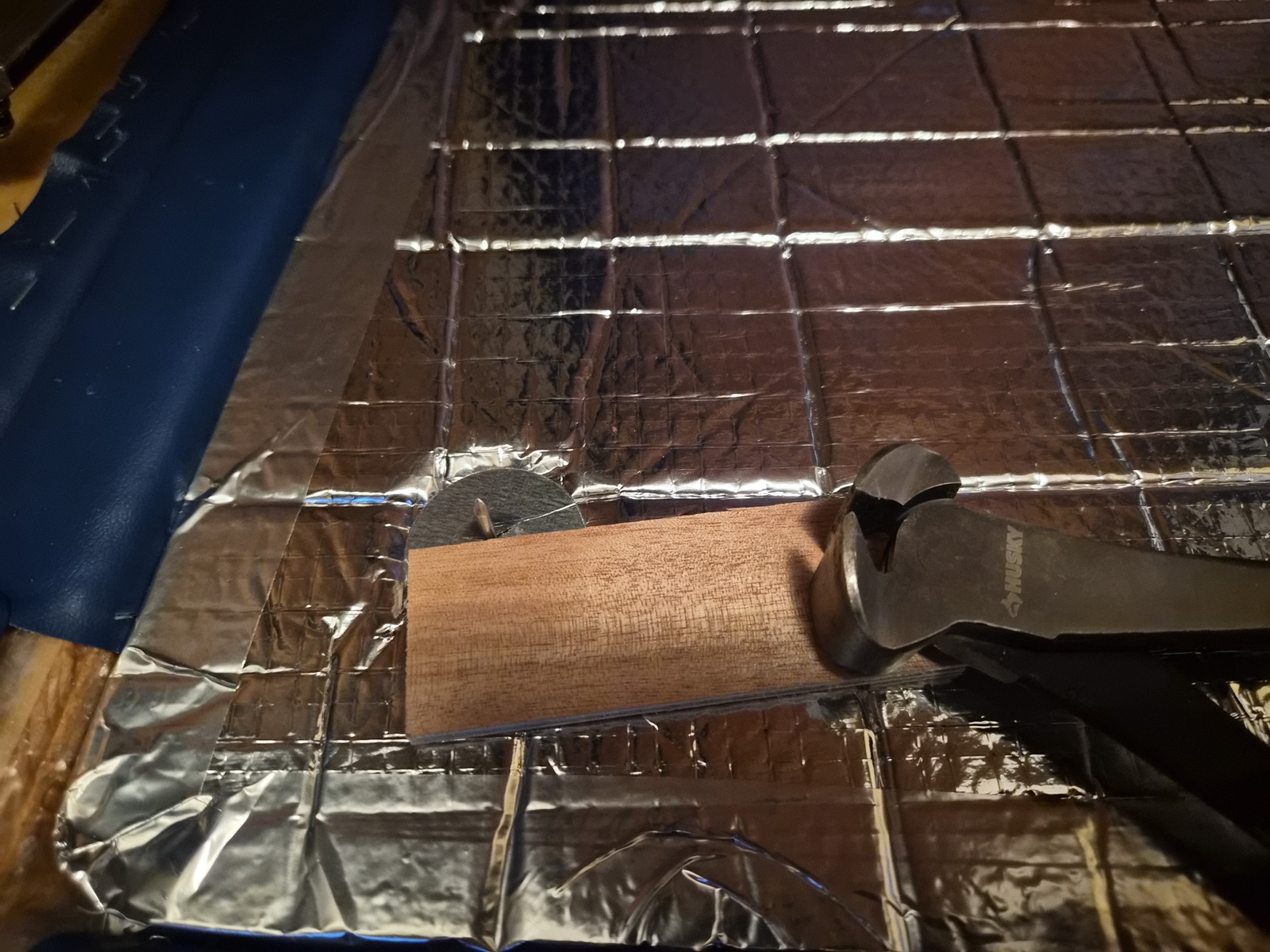
The instructions advise trimming each anchor pin to a height of 1/4 inch above each washer. I created a jig from a small piece of 1/4 inch plywood which I used as a guide to set the depth of my vertical cutting pliers.


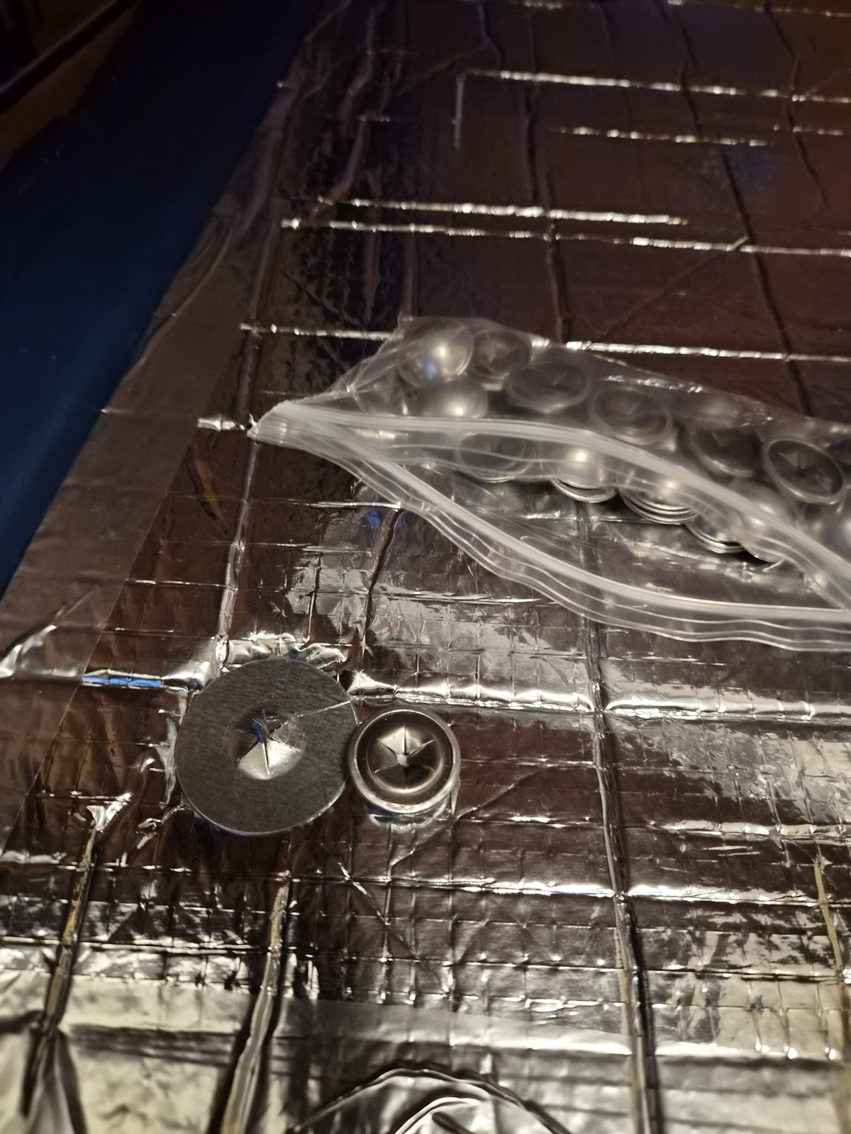
Once trimmed to a 1/4 inch, I ground the sharp tip left from the cutting process with a Dremel rotary stone and prepared to install the caps included in the kit.


One completed, twenty-nine to go.


Finished installation looks very clean.

I still want to add an over center latch on each side of the engine cover to keep the lid from potentially bouncing in rough water. I have a pair on order.

Please Log in or Create an account to join the conversation.

1971 Glasspar Newport Cruiser - Rejuvenation 2 months 1 week ago #149531

Nice work.
The following user(s) said Thank You: Larsspar

Please Log in or Create an account to join the conversation.

1971 Glasspar Newport Cruiser - Rejuvenation 2 months 2 days ago #149546

  • Larsspar
  • Larsspar's Avatar Topic Author
  • Offline
  • Senior Boarder
  • Senior Boarder
  • Posts: 248
  • Karma: 5
  • Thank you received: 21
I appreciate the support, Doug. Many thanks!

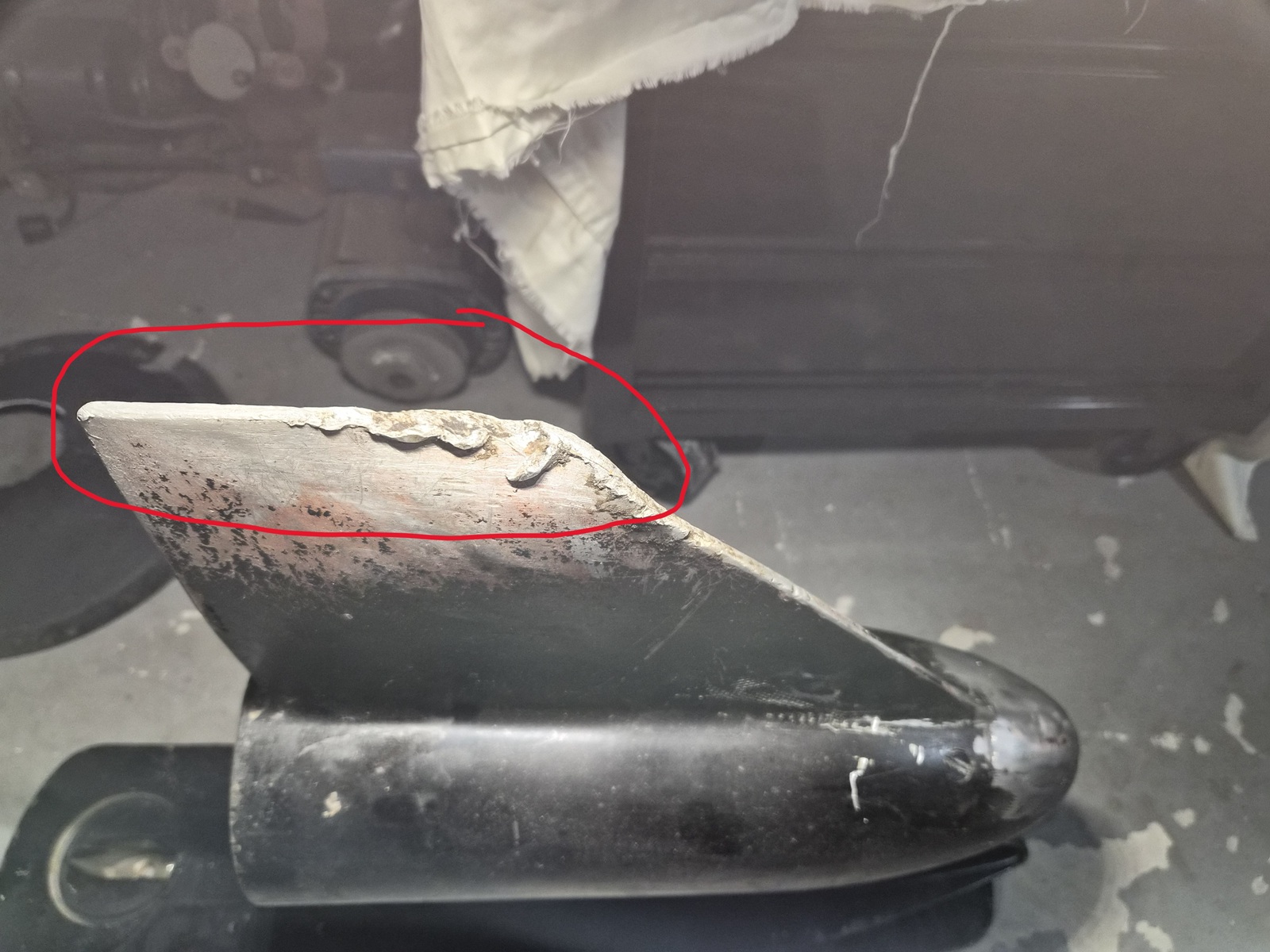
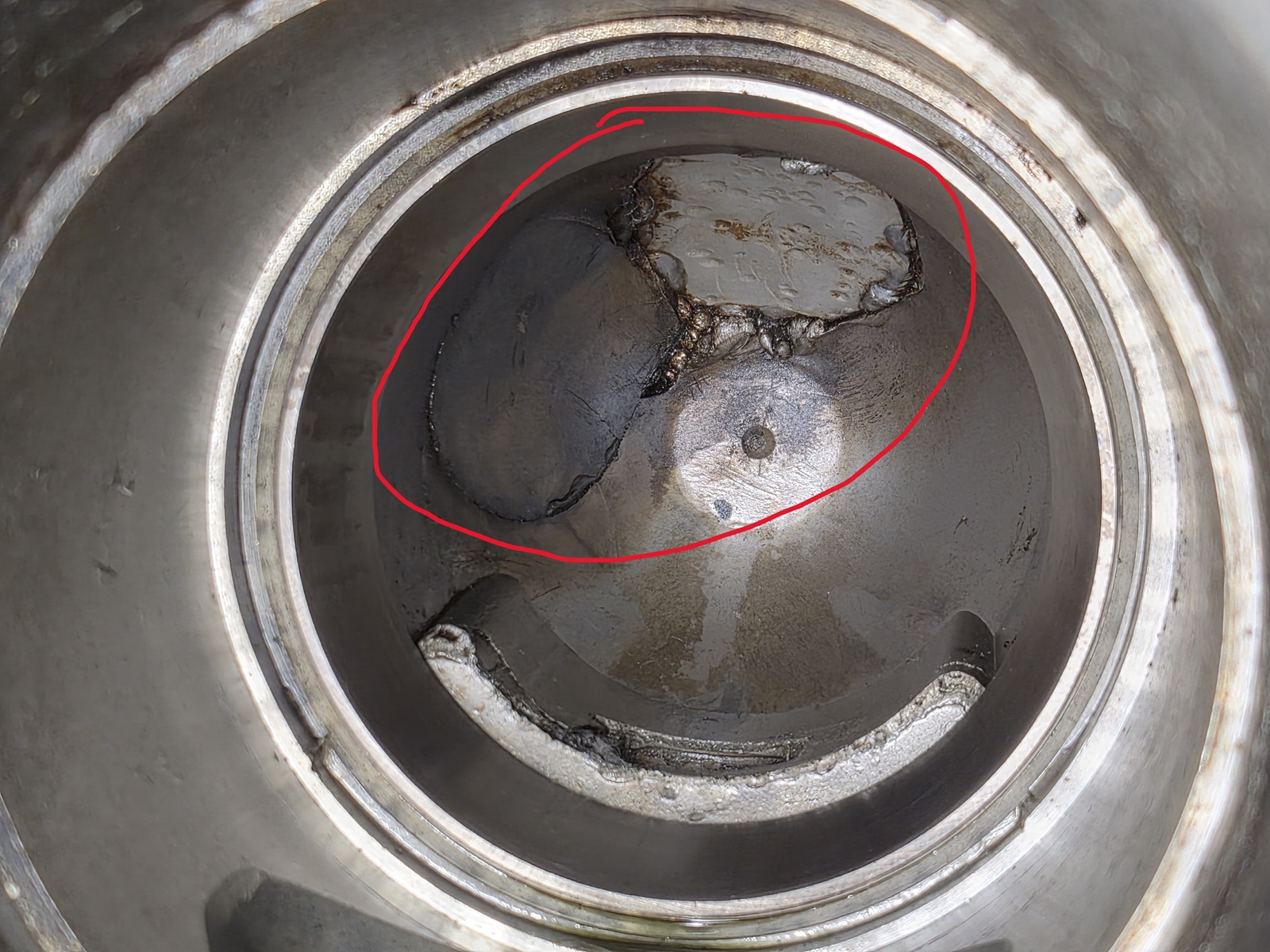
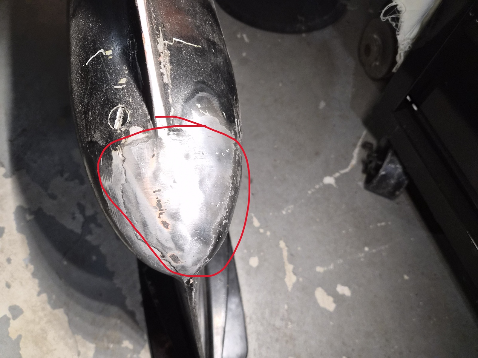
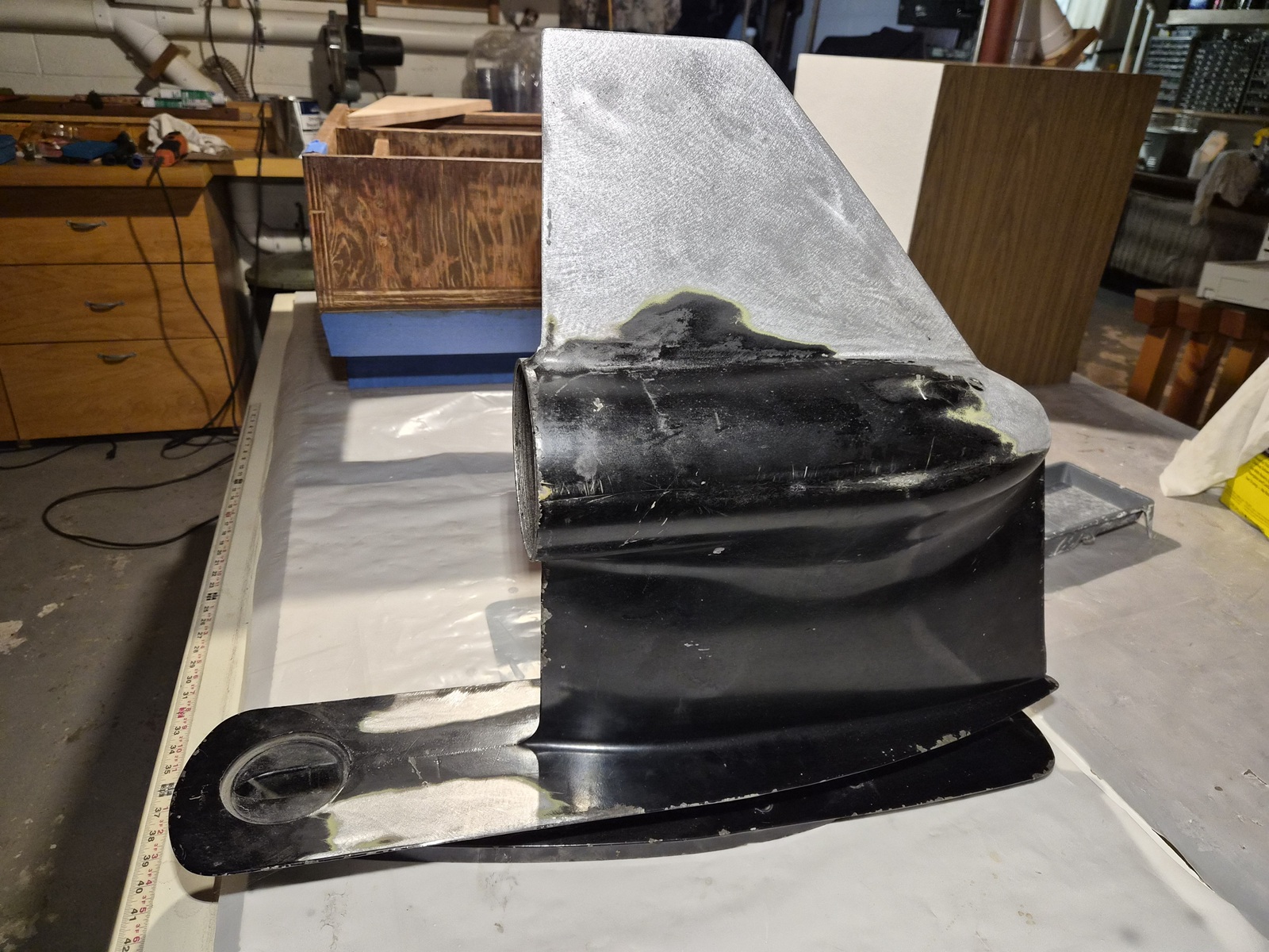
What is now several years ago, as I was just starting this project I was documenting, disassembling, and inspecting all the components, I was devastated to determine the lower unit of the drive had been majorly damaged and hastily repaired. This explained why I found some water in the drive oil when I drained it.

Earlier this spring I found an excellent partner in Randy at Precision Weld in West Bend, WI. He specializes in welding aluminum. Even better, he specializes in welding boats hulls, pontoons, boat engines, props, tanks, castings etc. Randy is far from the cheapest guy around, but after you see his work, I think you'll agree he's an artisan.


Revisiting the original inspection, the skeg had a major collision with a rock. (I found this out when I turned up to pick up the boat)


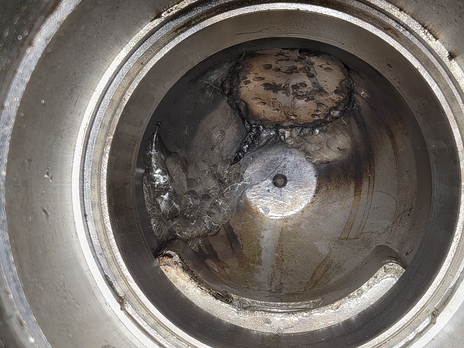
Most troubling, I determined the nose had been completely smashed open. I couldn't see this until I removed the bearing carrier.


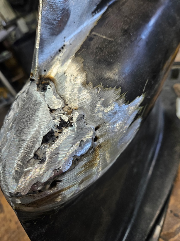
I used a rotary brush to remove paint and filler and found this.


Not a good welding job.


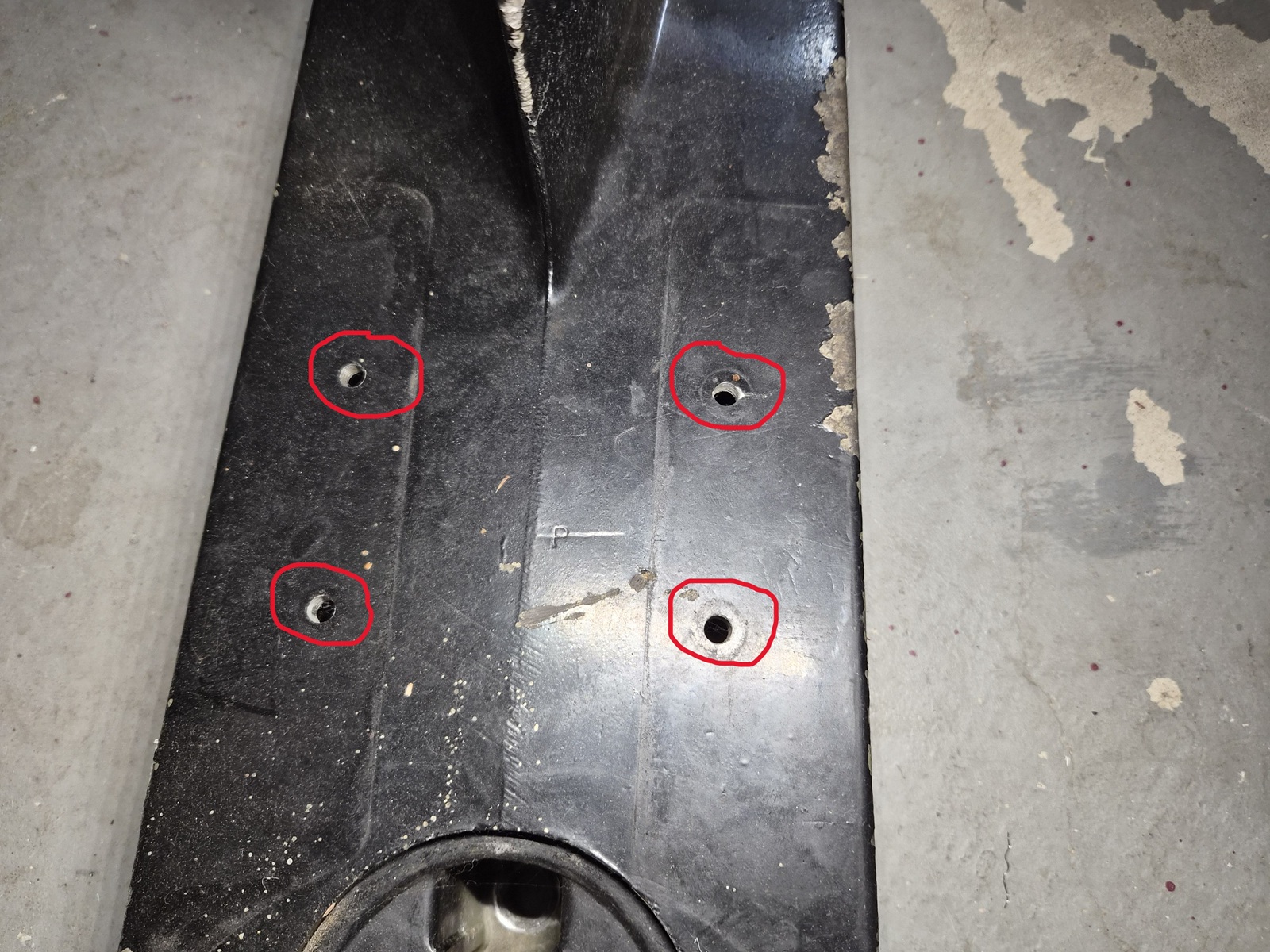
Aside from the nose, I asked Randy to fill in these holes which were drilled for an aftermarket fin.


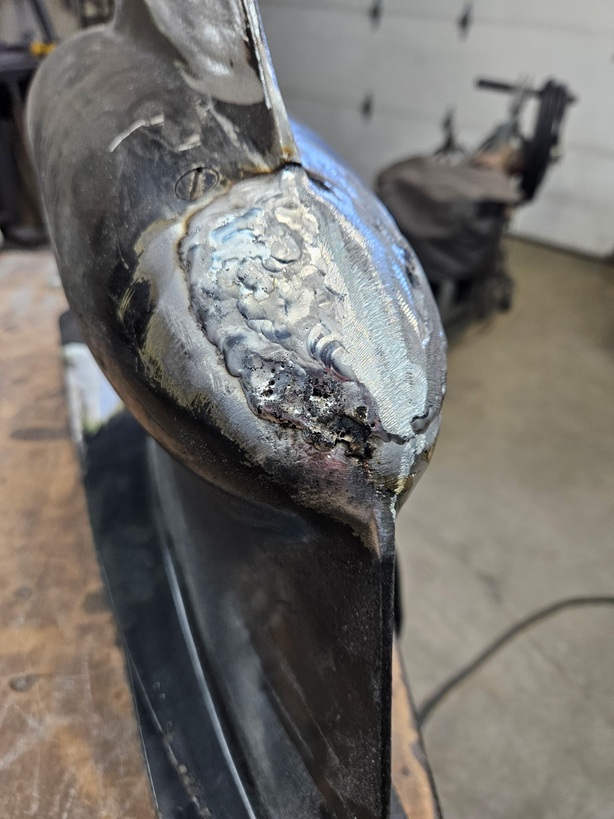
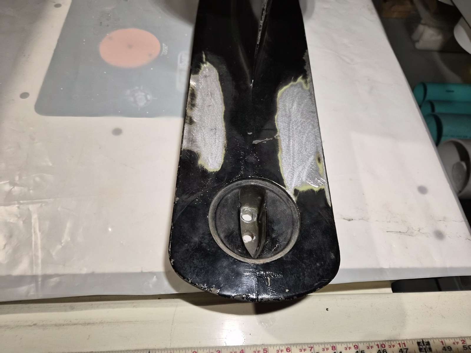
Randy reinforced the original welds as needed.


Filled in the bolt holes.


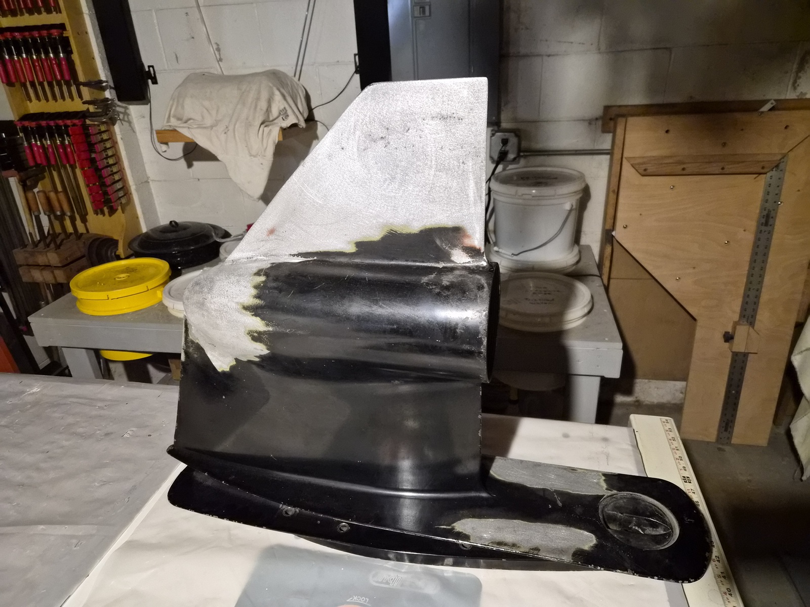
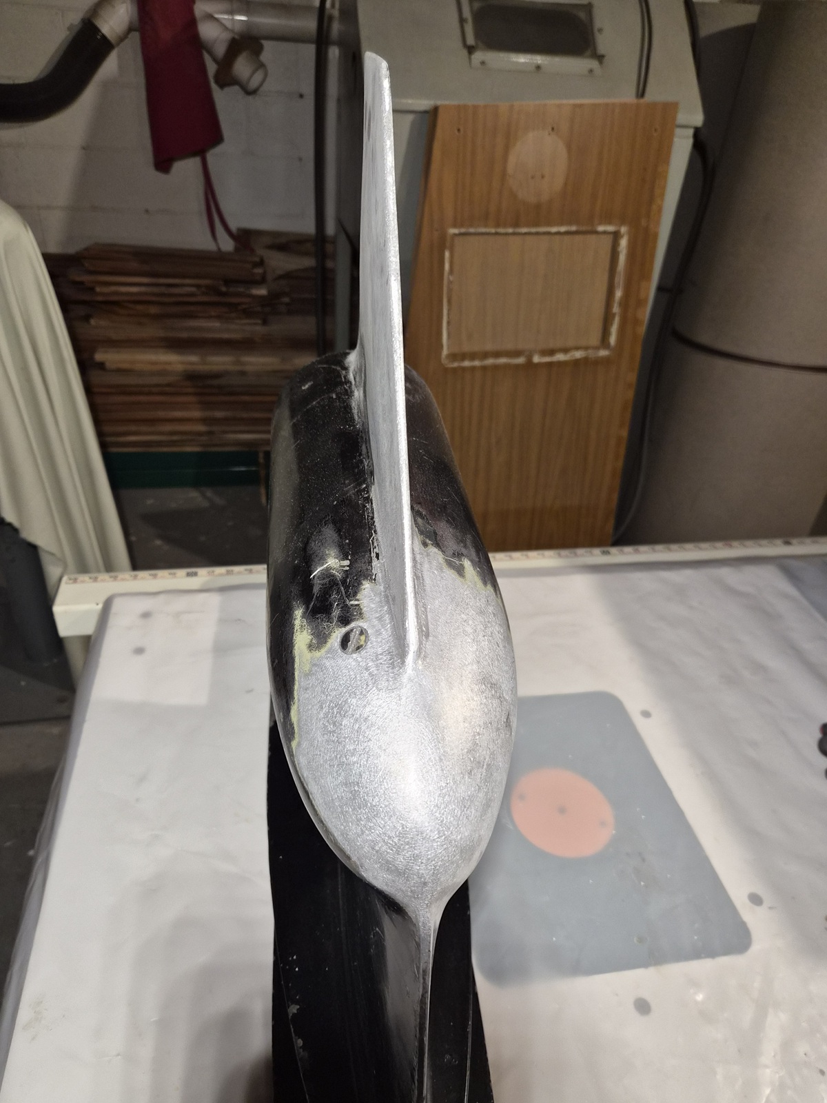
Randy cold hammered the skeg back into form and smoothed it. He explained that you should not/do not use heat for this process when working with aluminum. Just hammer and anvil.


Port side.


I got to say the nose looks near brand new..........

Please Log in or Create an account to join the conversation.

1971 Glasspar Newport Cruiser - Rejuvenation 2 months 1 day ago #149548

One trip back to Lake of the Woods or Rainy L, I forget now & it could look just like before.

Please Log in or Create an account to join the conversation.

1971 Glasspar Newport Cruiser - Rejuvenation 2 months 1 day ago #149550

Lower unit looks good now!
The following user(s) said Thank You: Larsspar

Please Log in or Create an account to join the conversation.

1971 Glasspar Newport Cruiser - Rejuvenation 1 month 4 weeks ago #149552

  • Larsspar
  • Larsspar's Avatar Topic Author
  • Offline
  • Senior Boarder
  • Senior Boarder
  • Posts: 248
  • Karma: 5
  • Thank you received: 21
The story told to me was the boat was purchased and lived its glory days on Lake of the Woods in a nice boat house. Its last and more unfortunate days were spent on Rainy Lake. I believe the drive damage may have occurred while being towed around Rainy Lake.

Have been working on the seat pedestals.


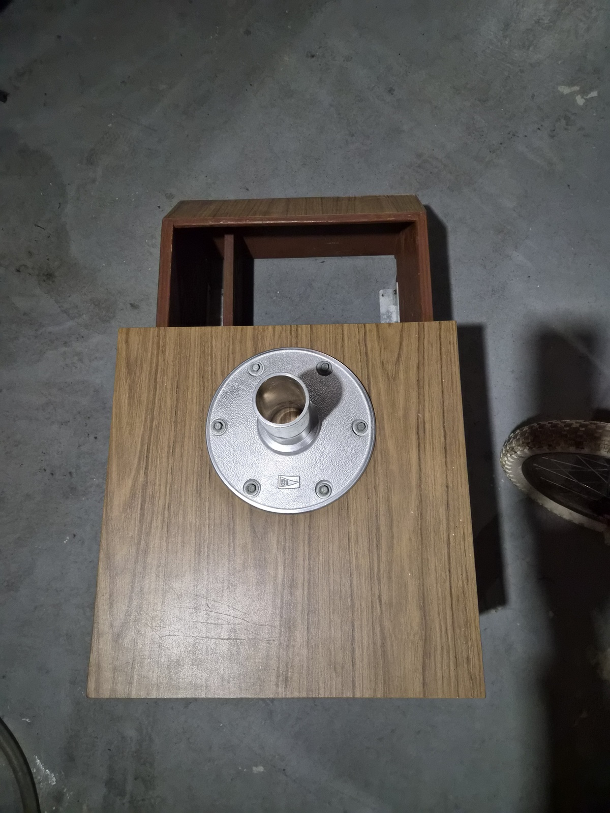
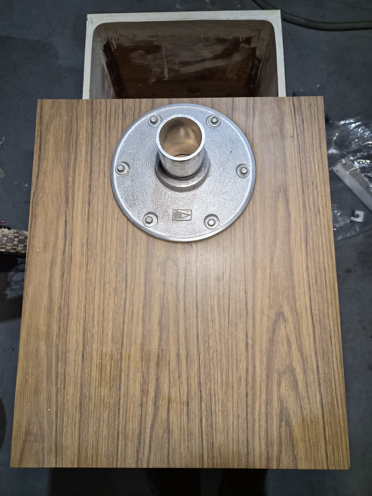
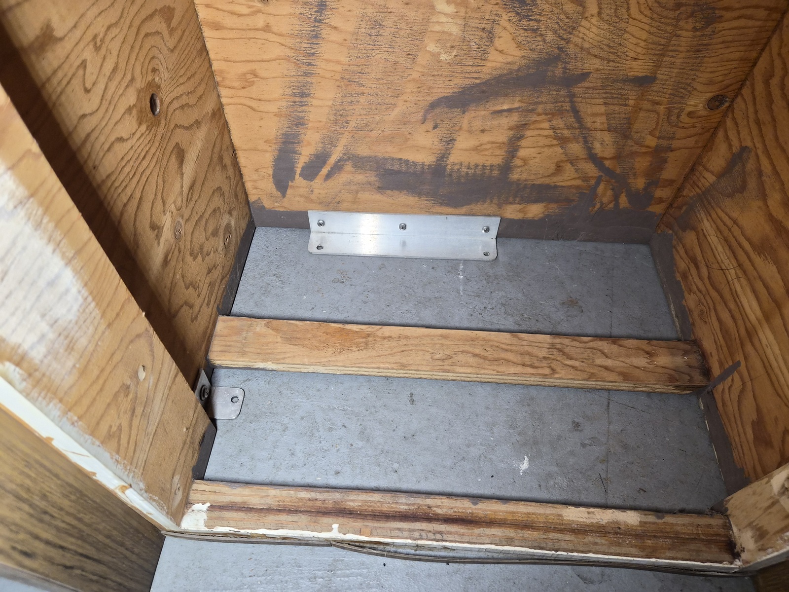
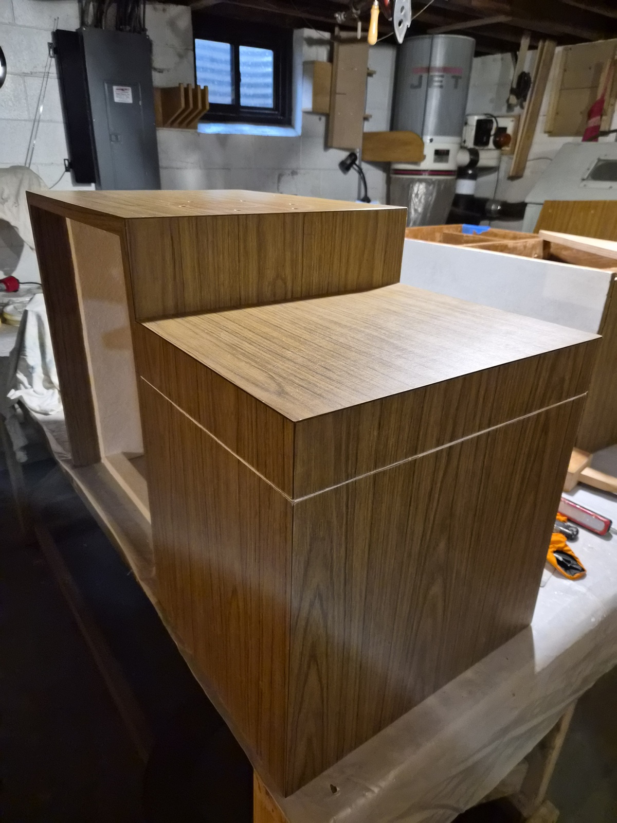
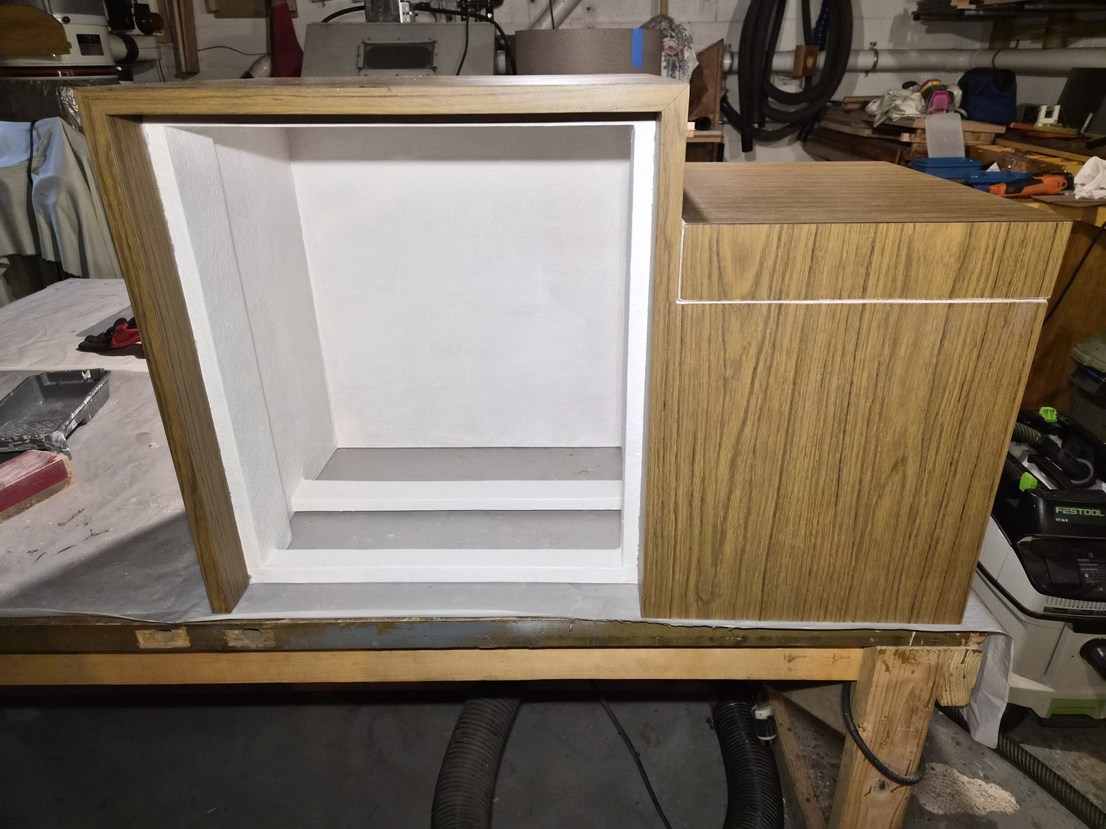
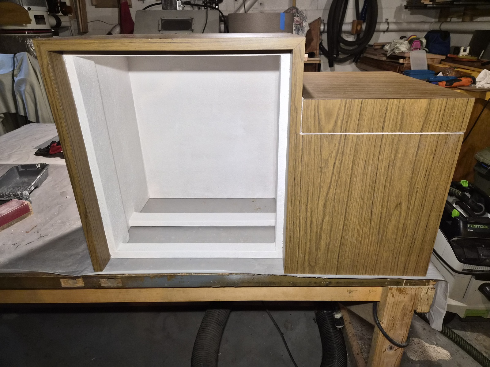
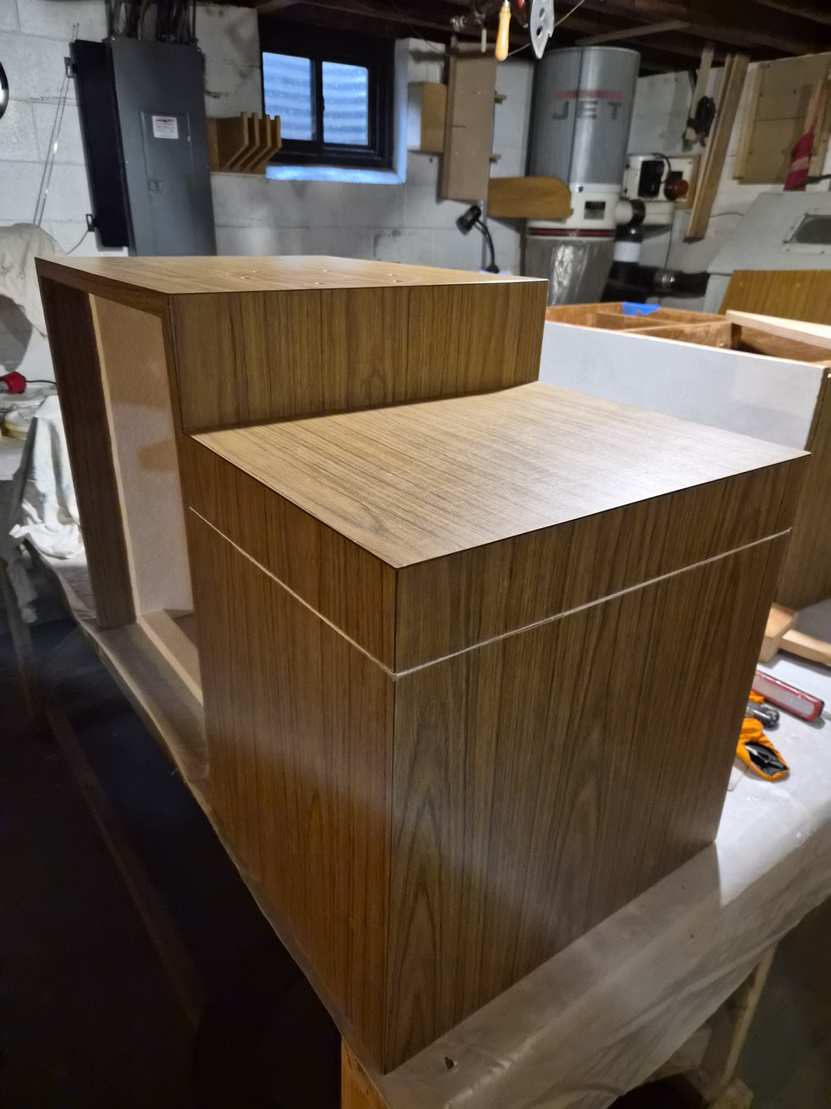
Port side contains a dry storage container under the footrest and an refrigerator/ice box. Starboard side holds batteries and minimal storage.


Removed mounting hardware from each cabinet


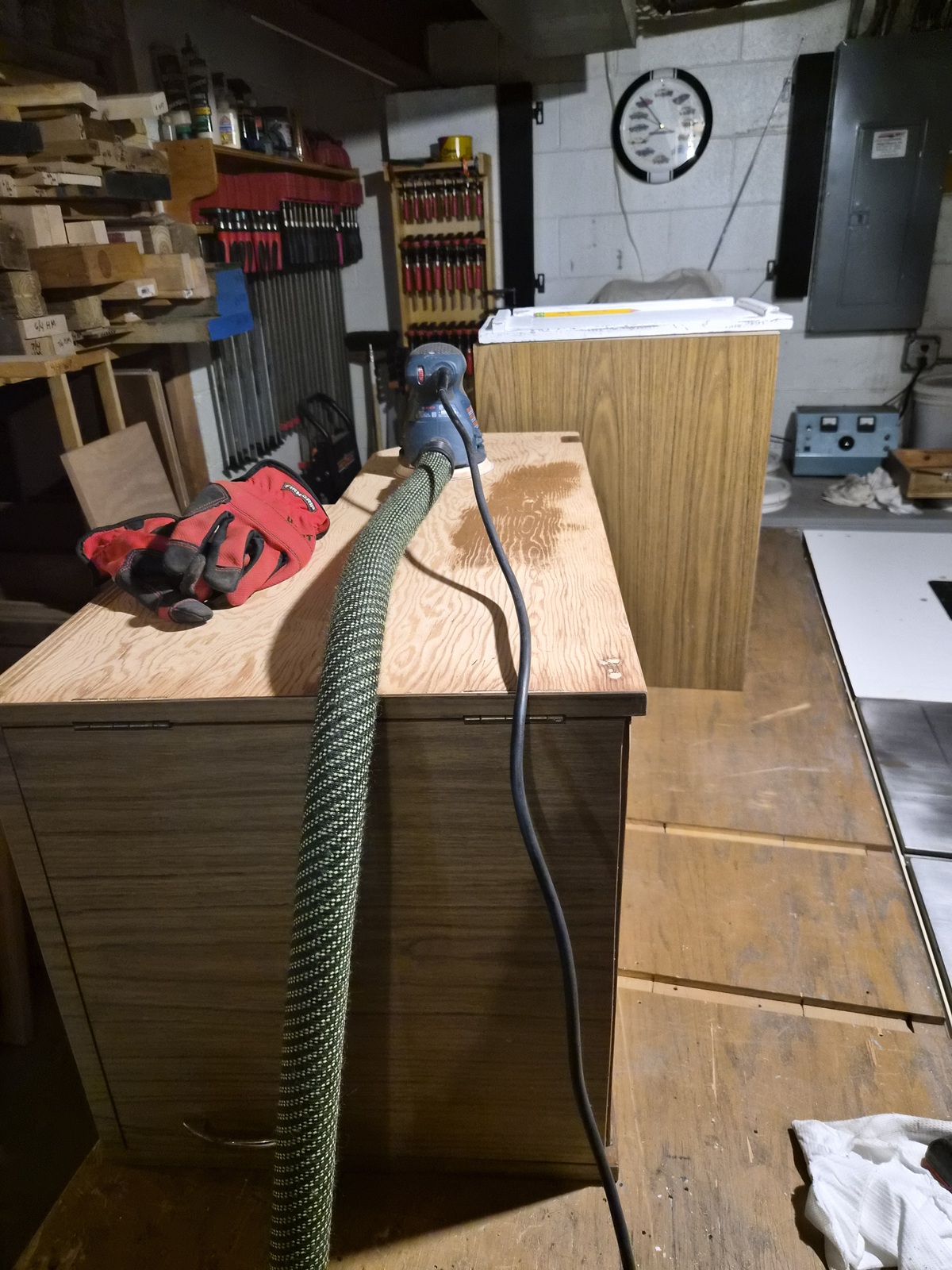
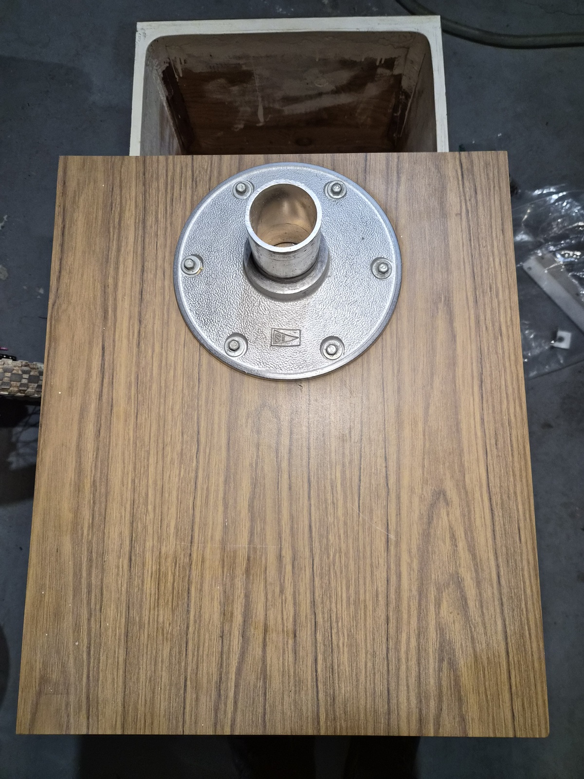
At some point, I'm guessing a previous owner painted the bare wood brown.


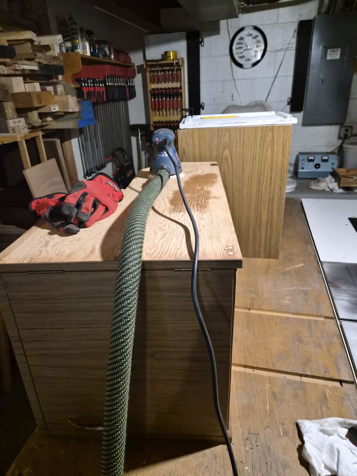
All exterior faces of the cabinets are covered with a durable wood grained Formica, except for the sides facing the hull. I sanded the paint off to get back to bare wood.


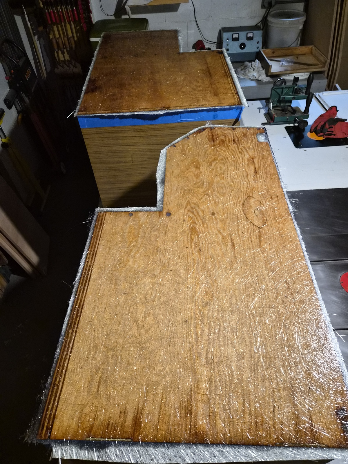
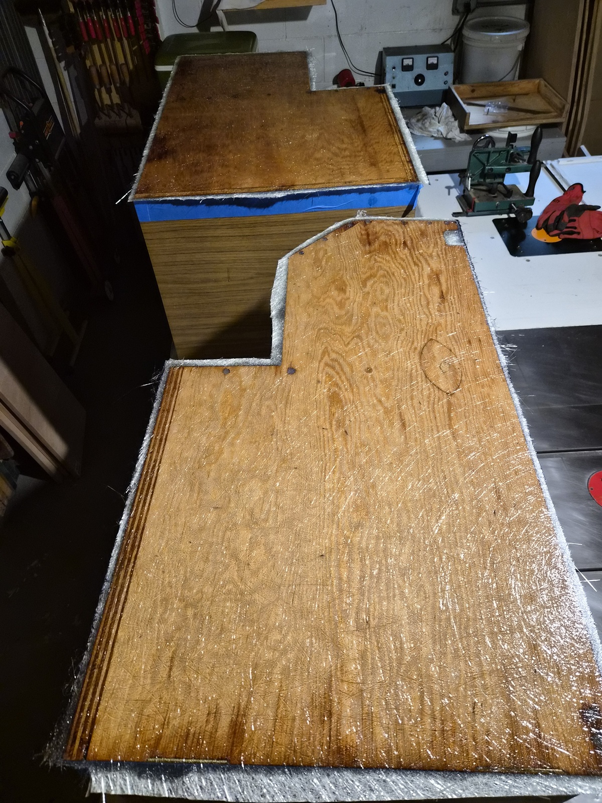
Applied a couple coats of laminating polyester resin and a layer of chop strand fiberglass.


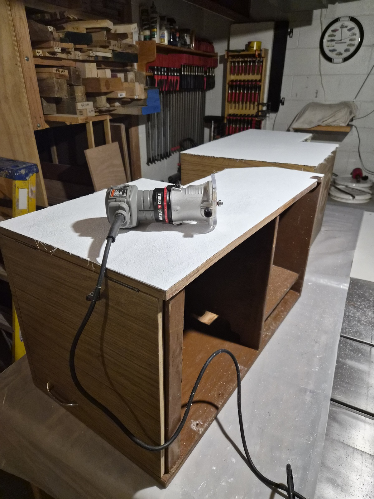
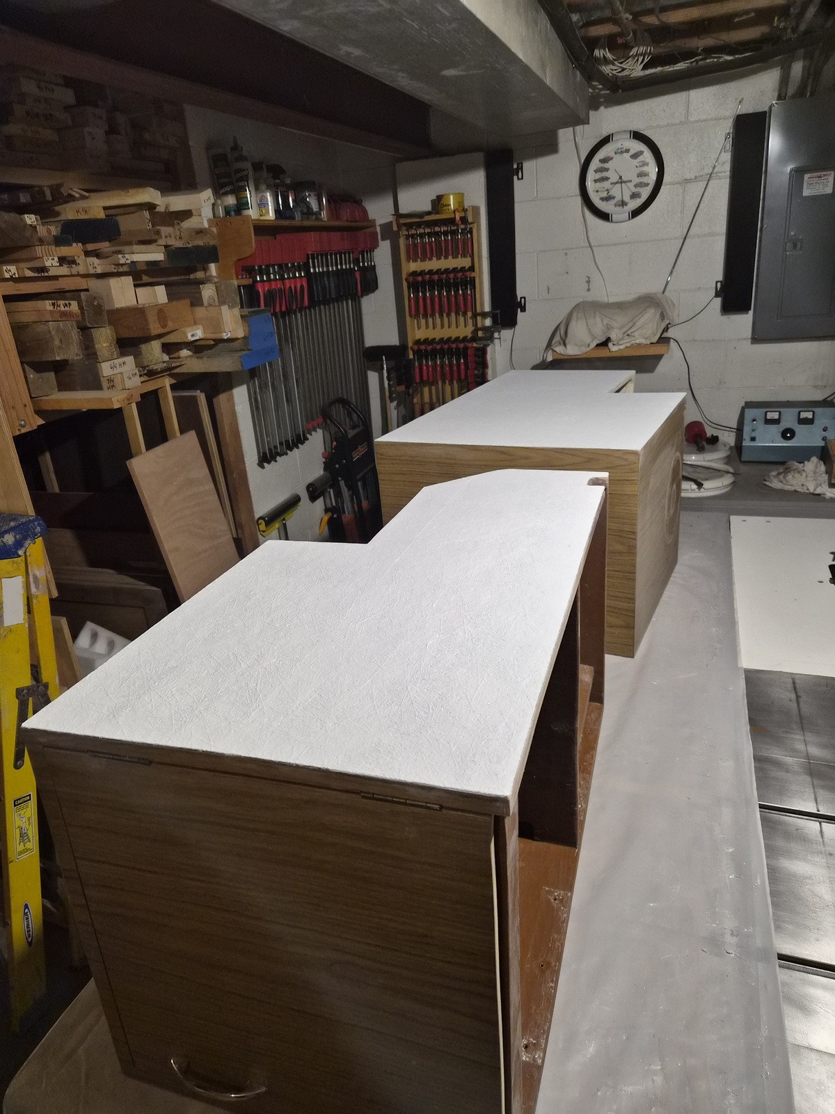
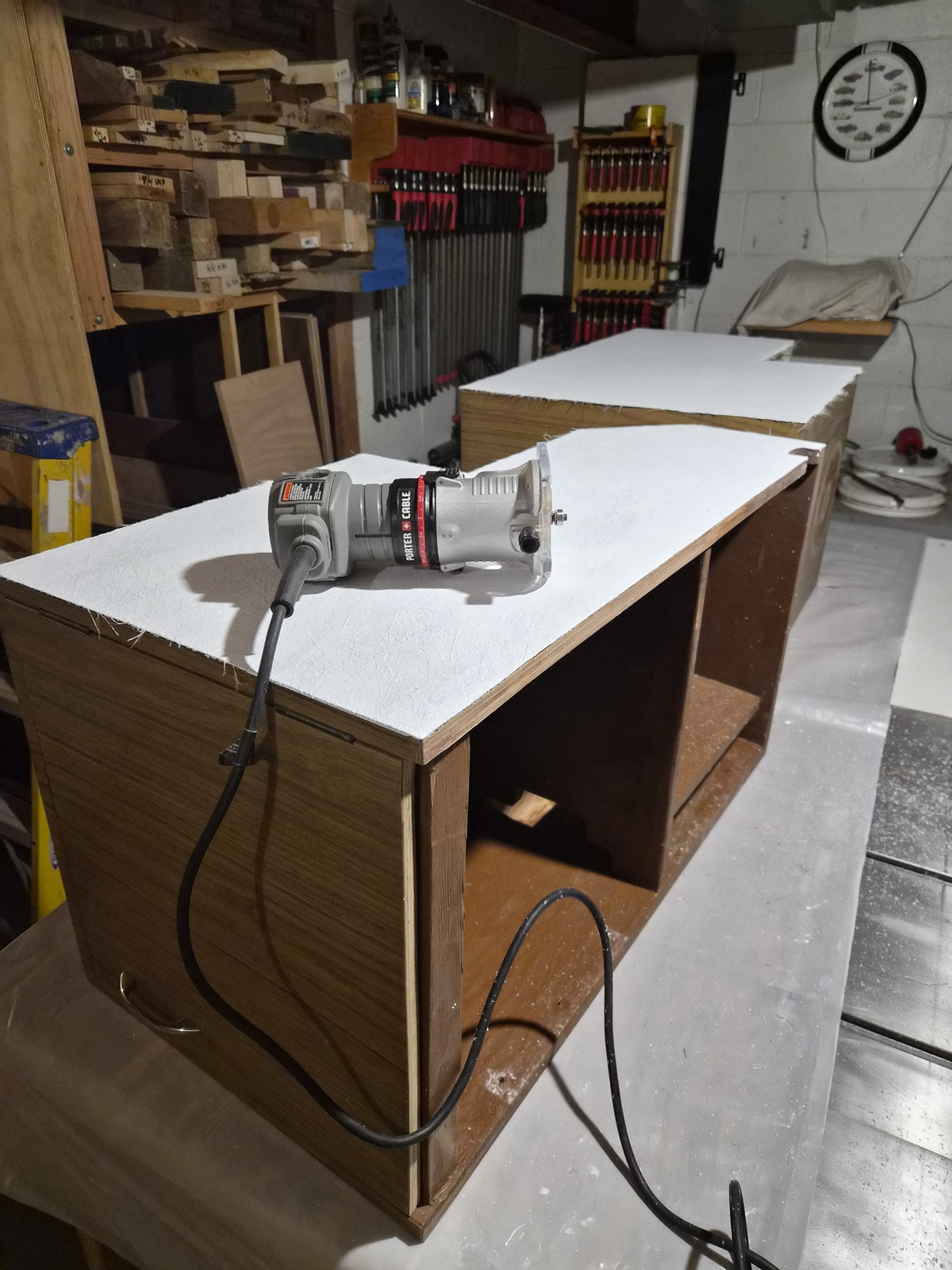
Applied a coat of gelcoat with wax added. Once dry, zipped the fiberglass flush to the cabinet with a flush trim router bit.


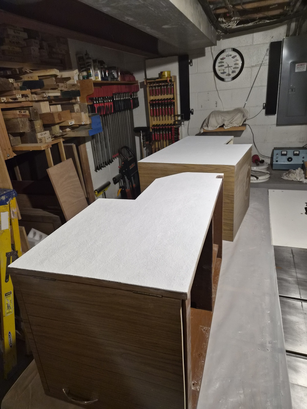
One side finished.


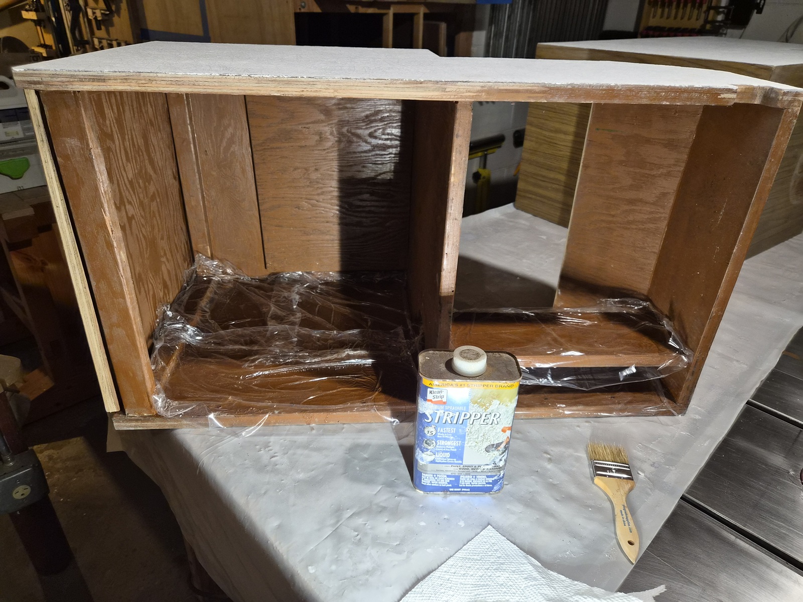
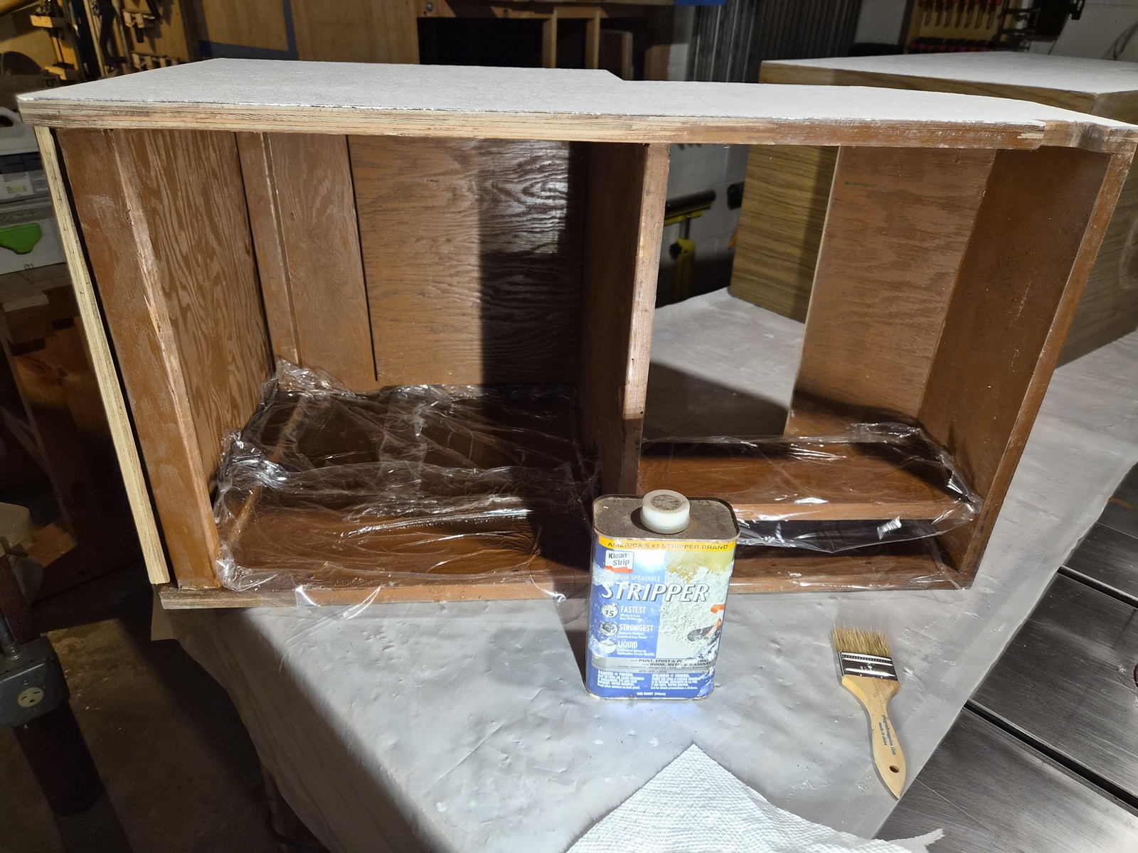
The interior of the starboard cabinet was painted brown. Started by applying paint stripper. Plastic wrap on top of the stripper helps the stripper effectiveness.


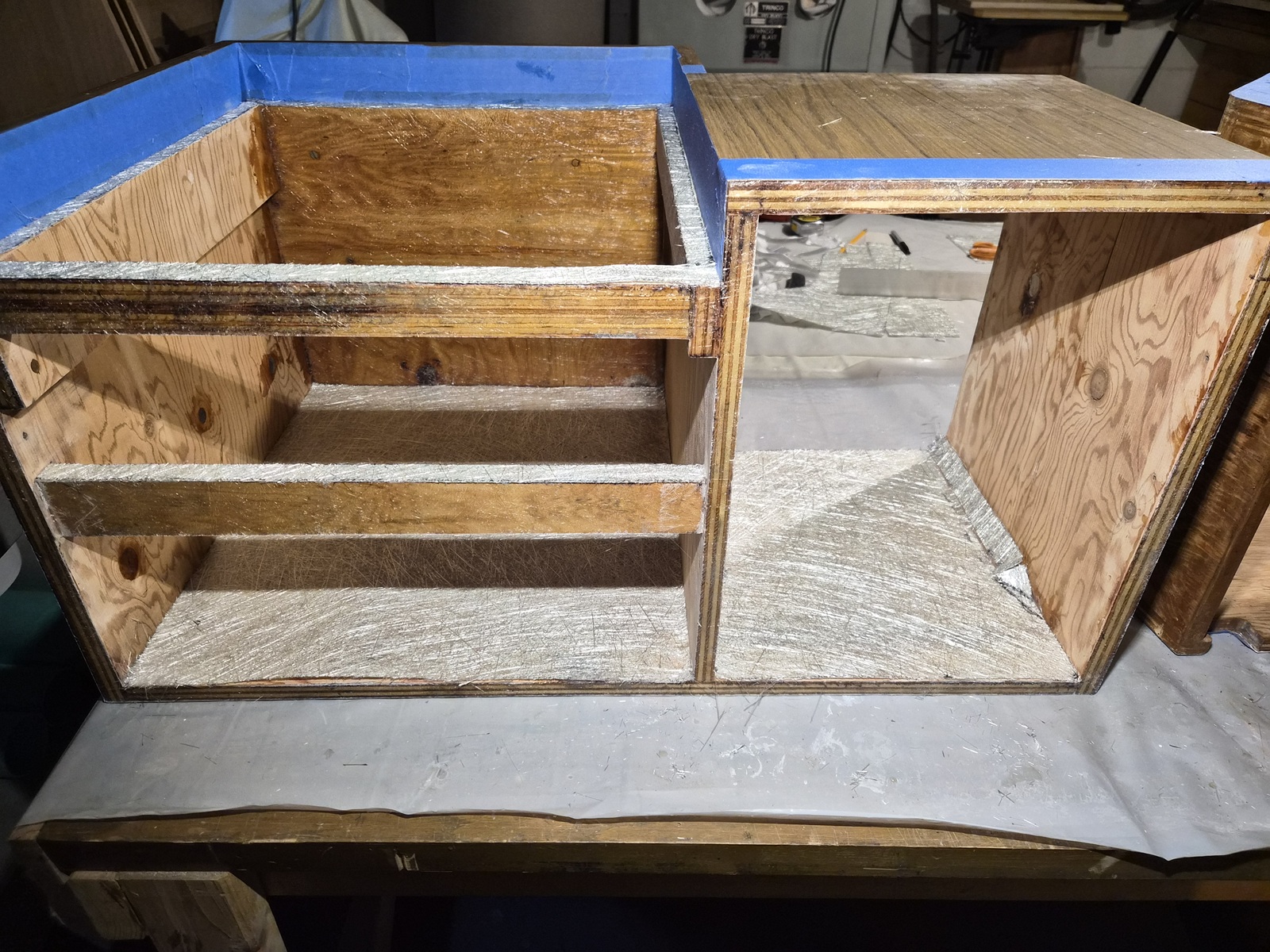
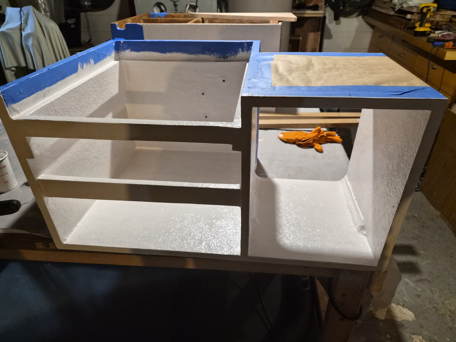
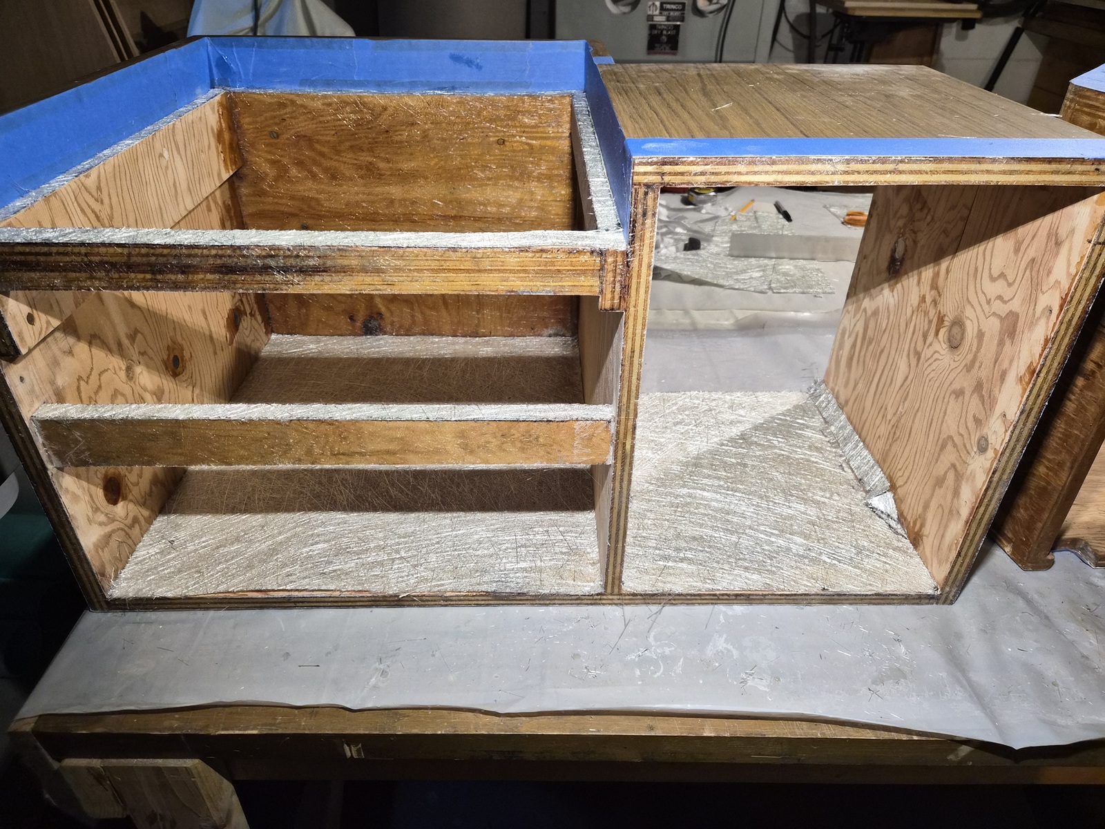
The port cabinet did not have as much paint, so was able to get away with a good sanding. I then cut and applied fiberglass to each surface one side at a time.


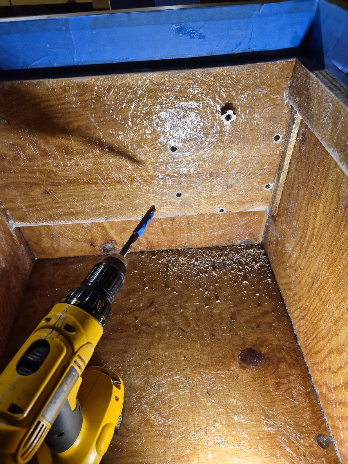
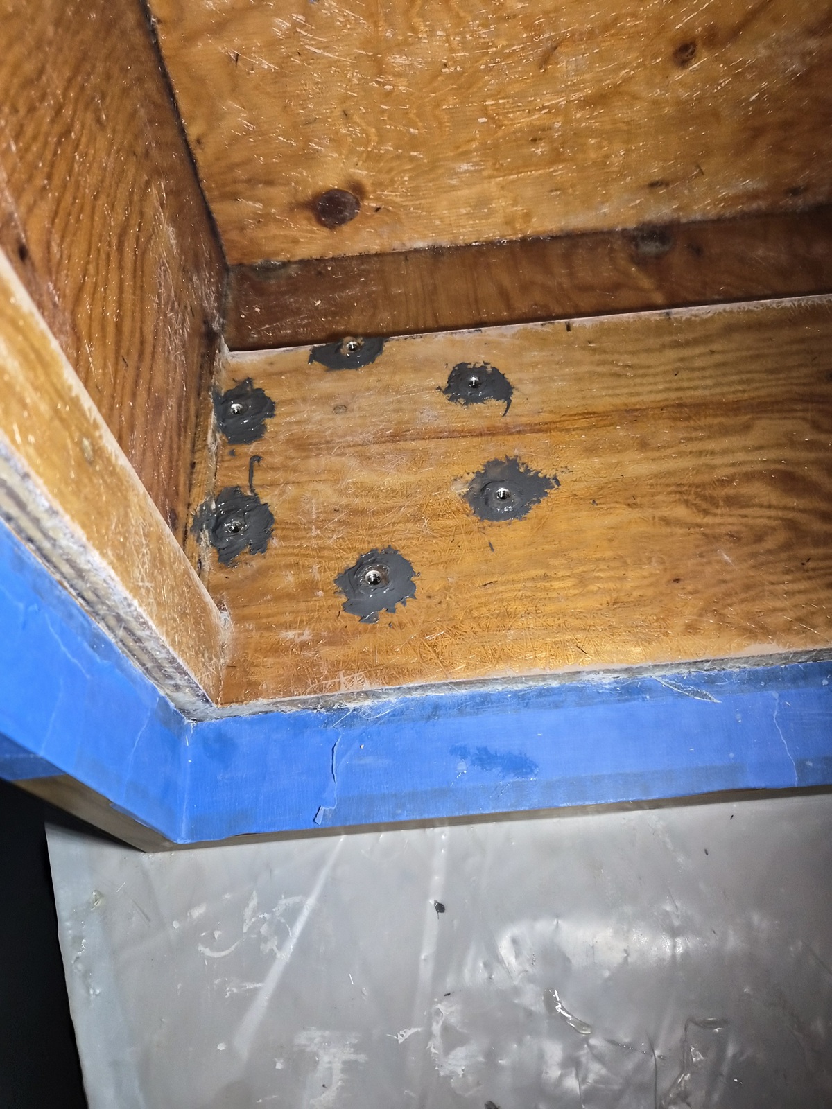
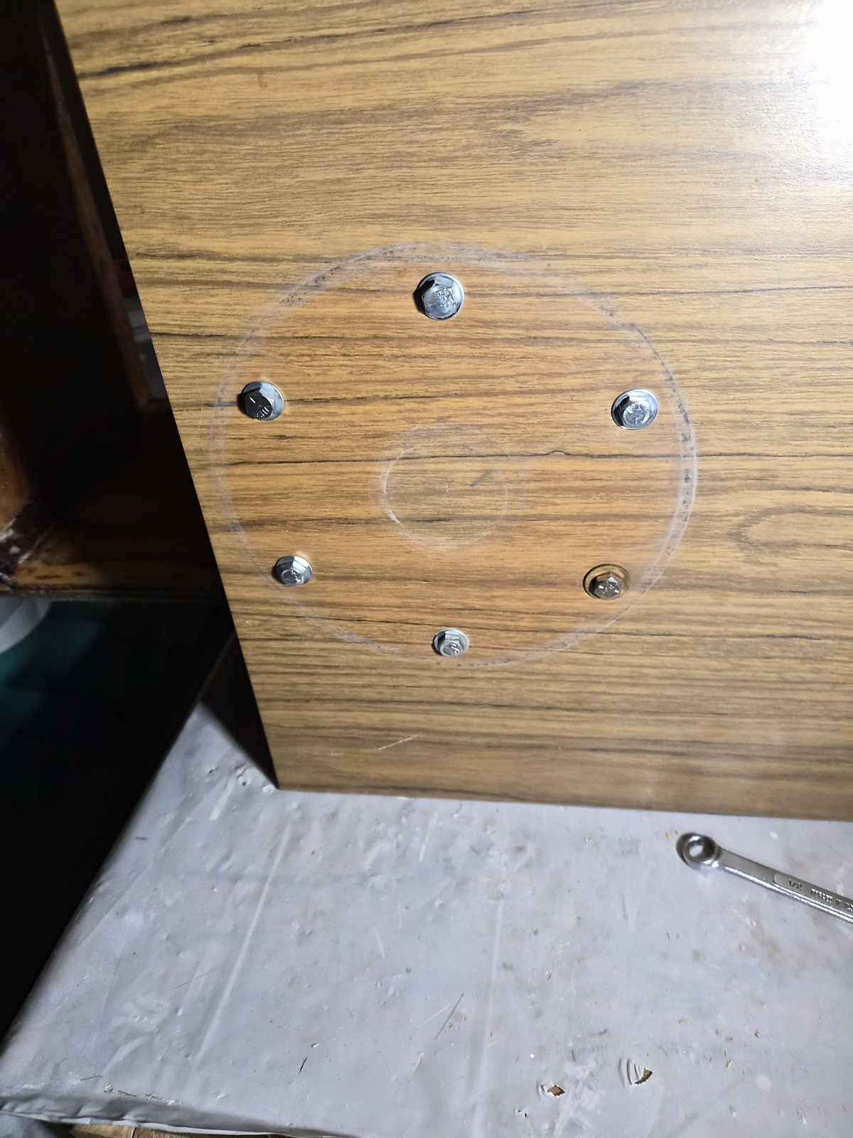
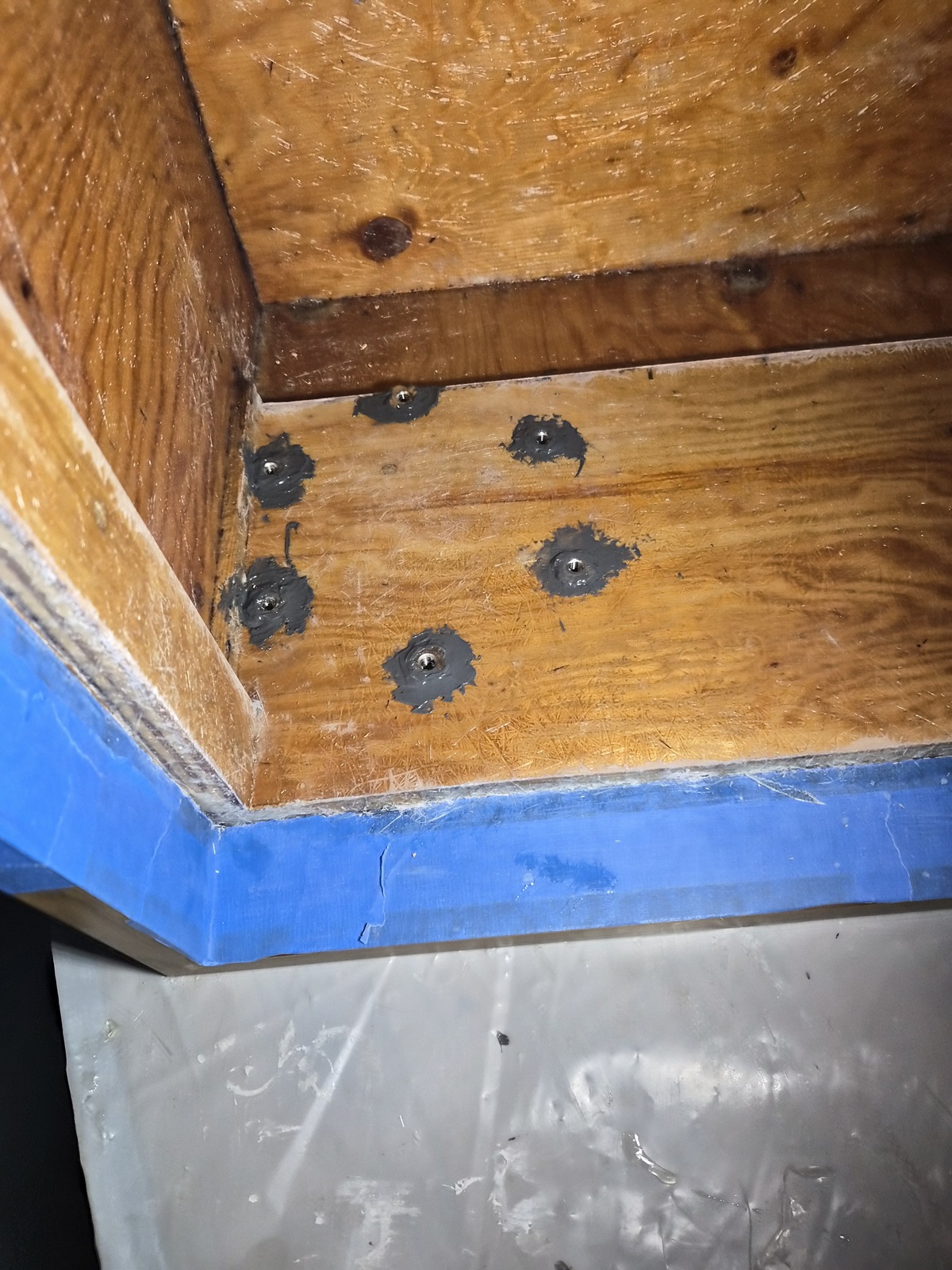
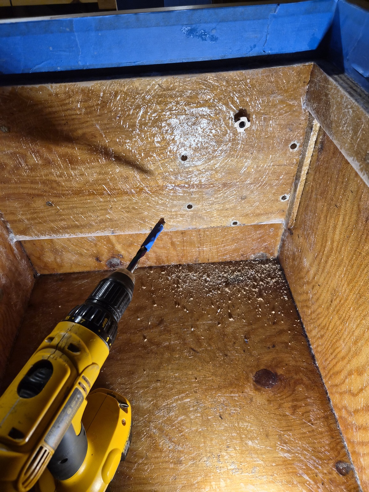
Once the fiberglass was complete, drilled slightly larger holes to accommodate t-nuts.


The t-nuts were glued in using J B Weld


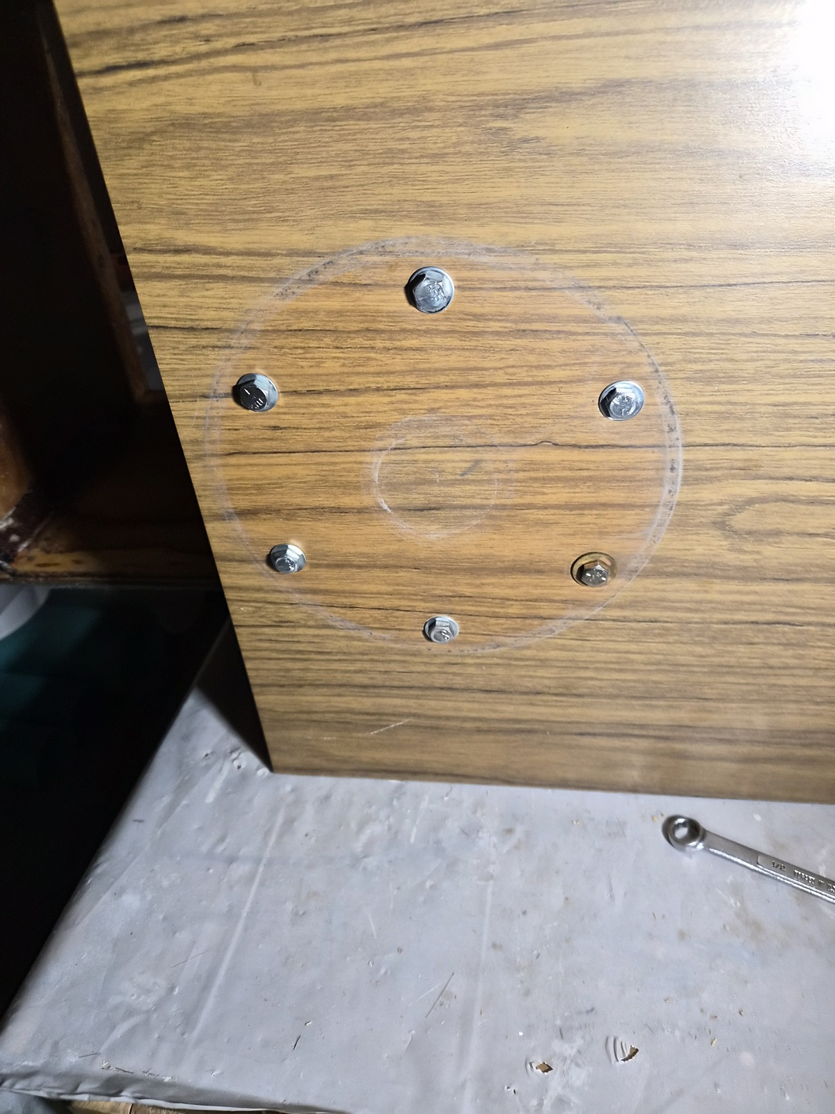
To ensure the t-nuts were seated, bolts and washes were installed and tightened.


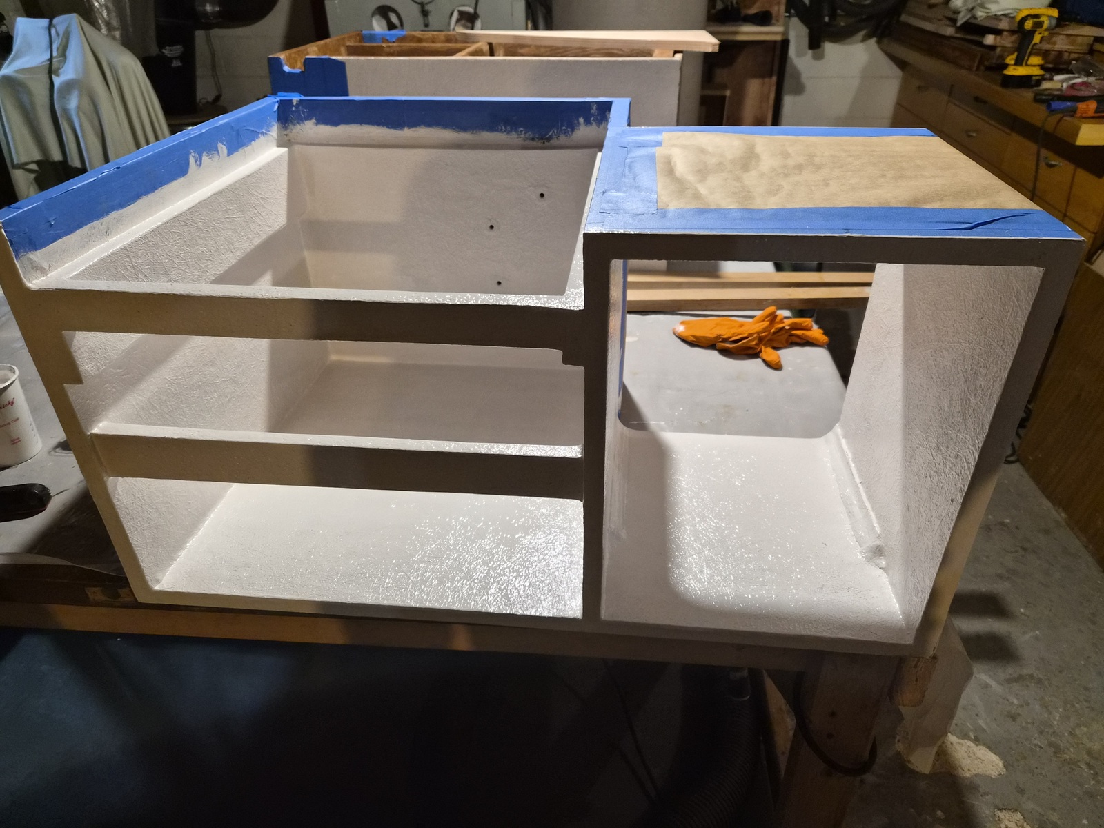
Two layers of gelcoat were applied to the surfaces not covered by Formica.


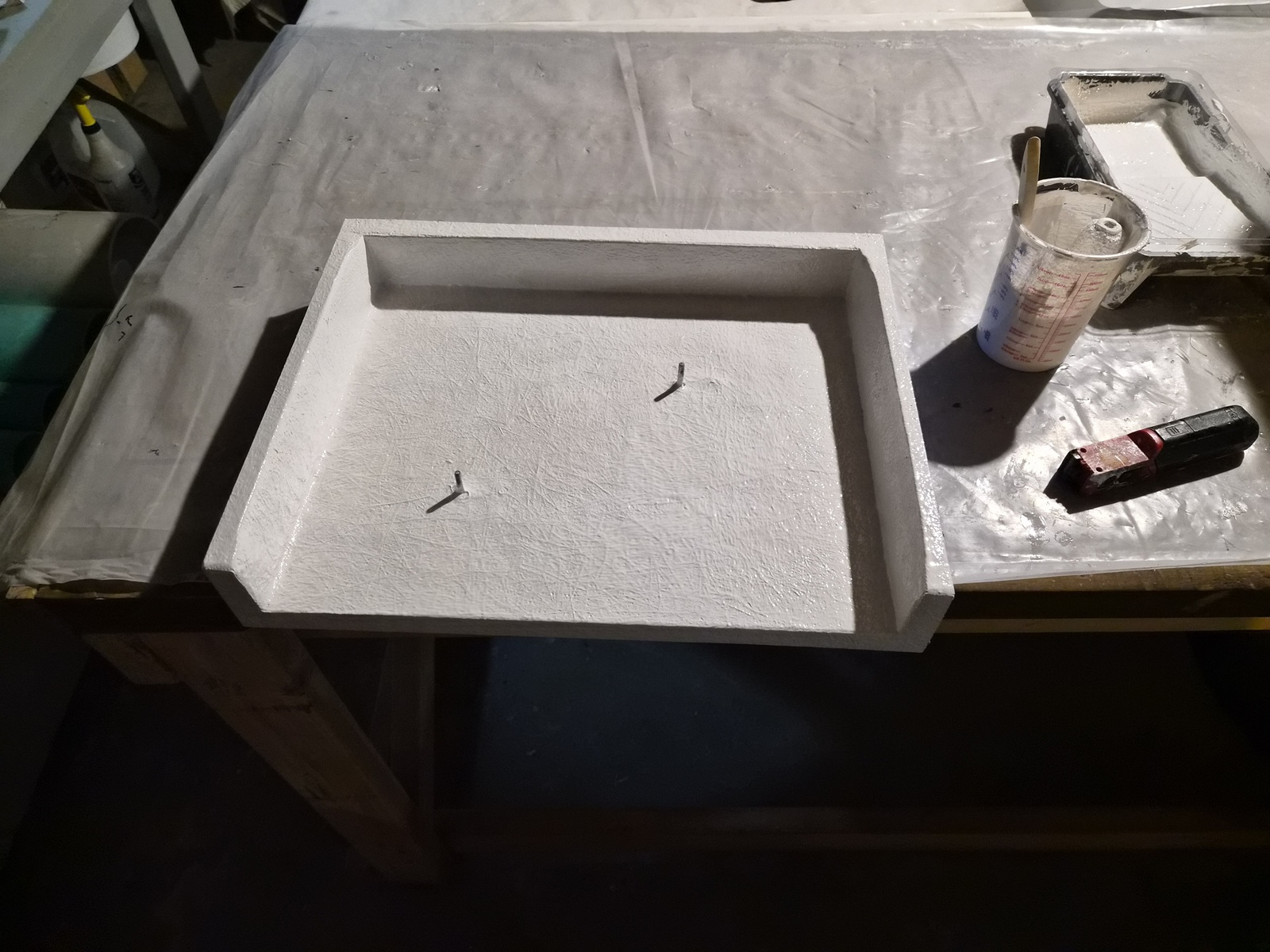
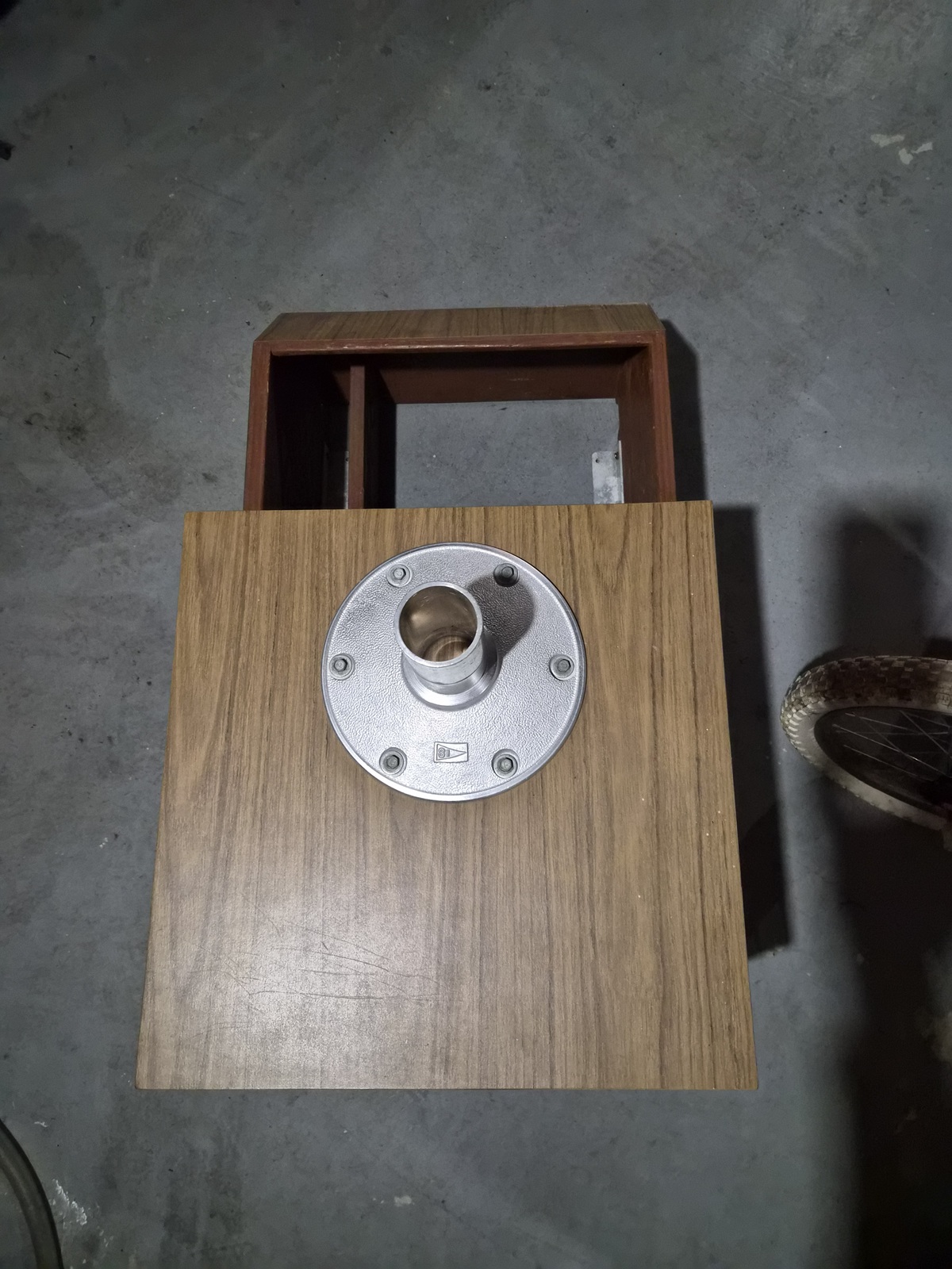
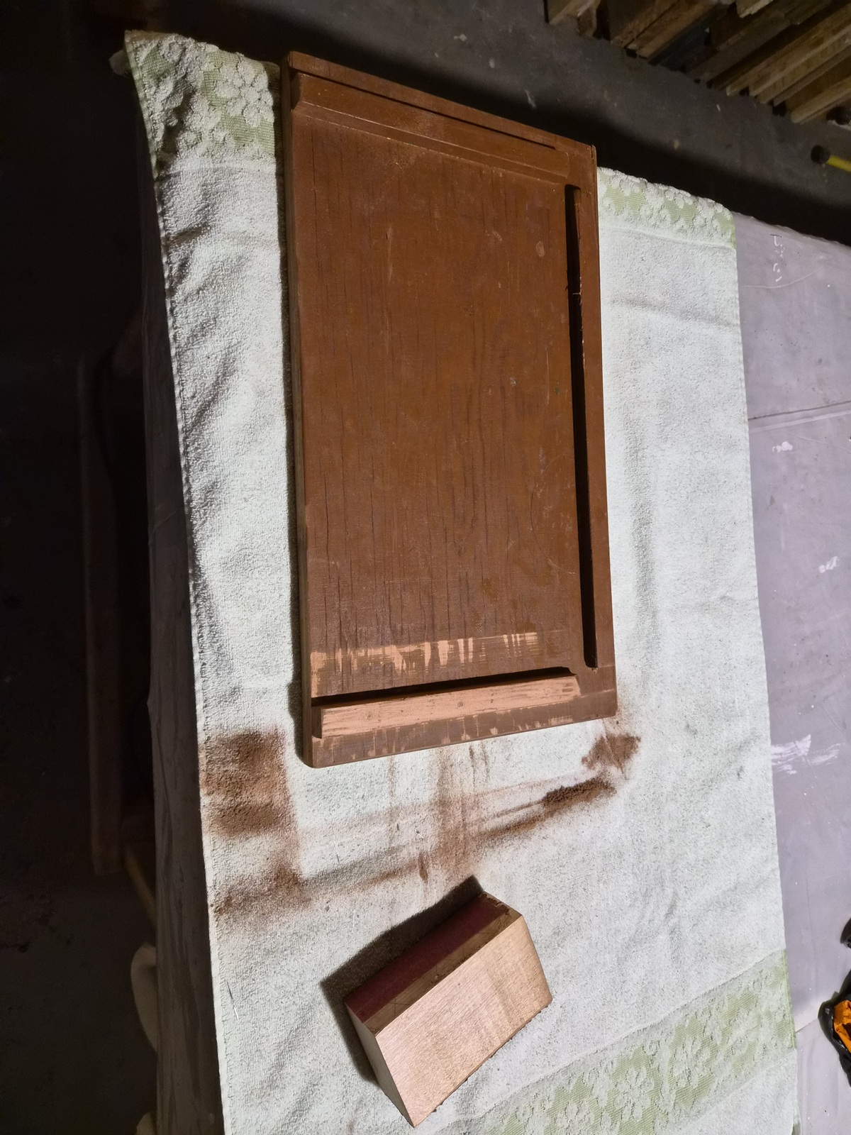
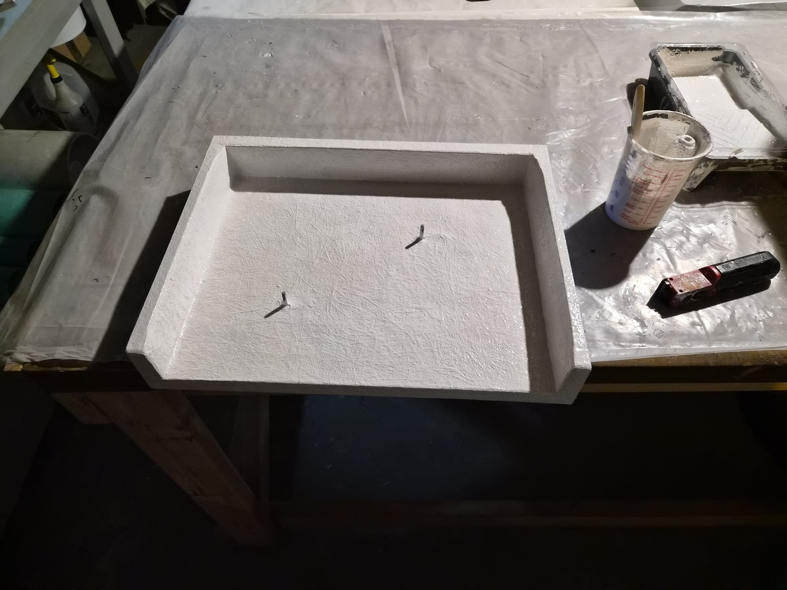
This is the lid for the dry storage compartment.


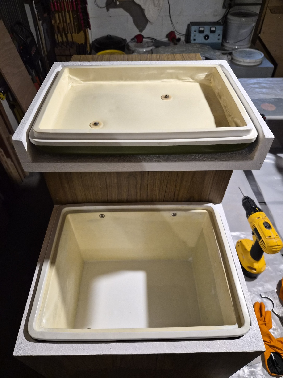
Prepared to install the recently renovated dry storage container.


Container lid bolted to the cabinet lid. Container slid into the cabinet and screwed into the cabinets through the sides.


The application of glass and gelcoat does present a white line along the mating surfaces. (not there previously)


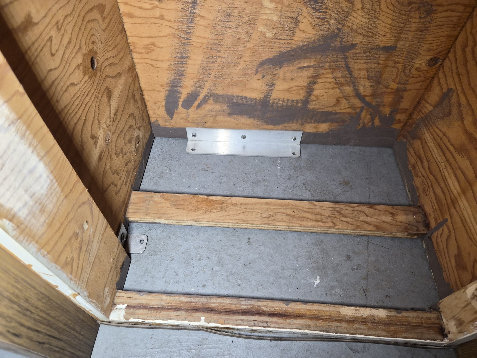
The refrigerator/ice box screws into the cabinet once the cabinet is mounted in the boat. I will add insulation to the recessed portions of the cabinet later. Plan is to add an Isotherm GE150 refrigerated plate to it. (more to come)

I'm still working on the starboard cabinet layout as I plan to add a house battery to it.

Please Log in or Create an account to join the conversation.

1971 Glasspar Newport Cruiser - Rejuvenation 1 month 1 week ago #149564

  • Larsspar
  • Larsspar's Avatar Topic Author
  • Offline
  • Senior Boarder
  • Senior Boarder
  • Posts: 248
  • Karma: 5
  • Thank you received: 21
Much work on this project is in progress. A lot of woodworking currently..

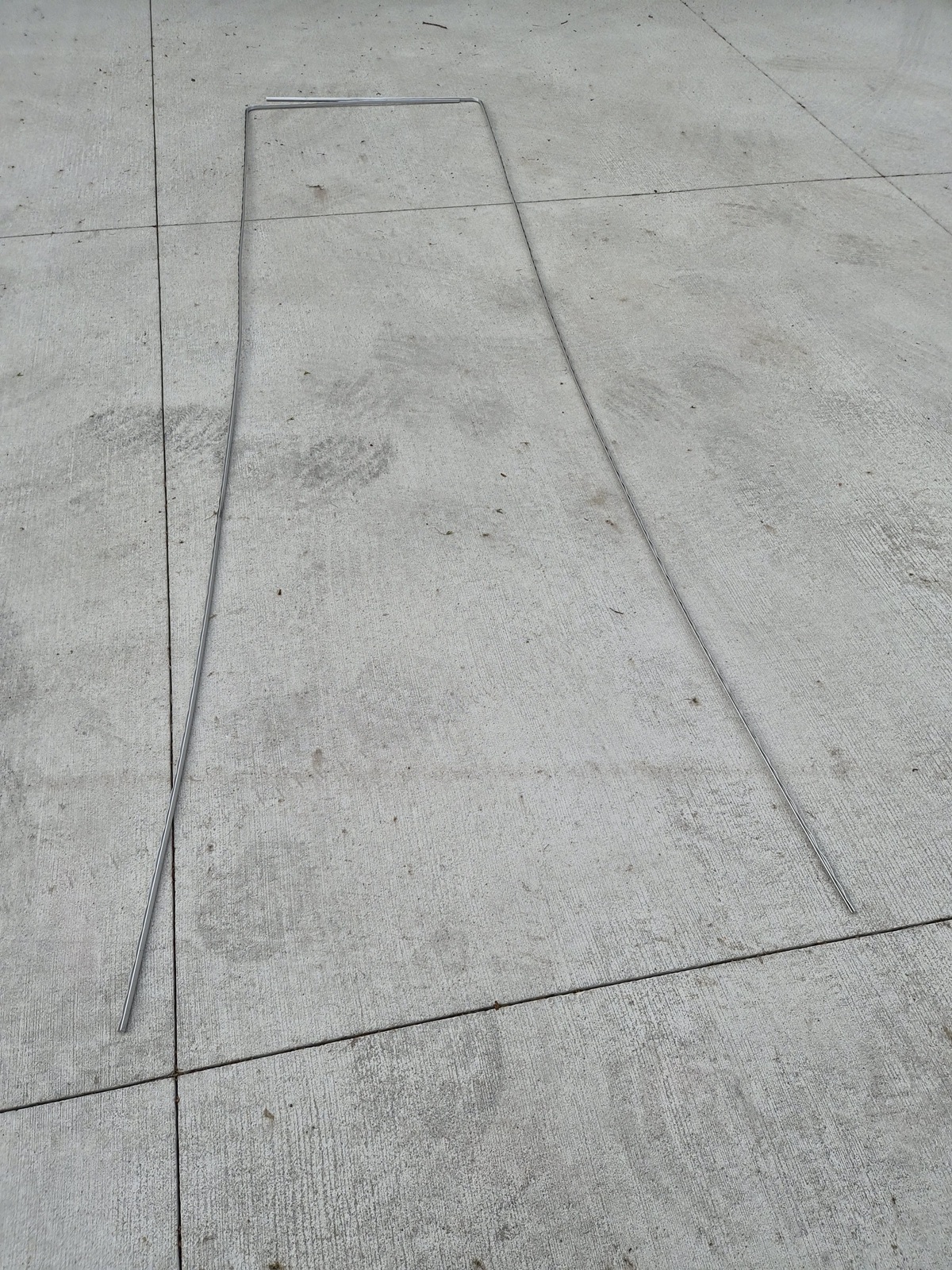
I had been carefully storing this channel trim in the basement. I was glad to get it out, installed, and undamaged.


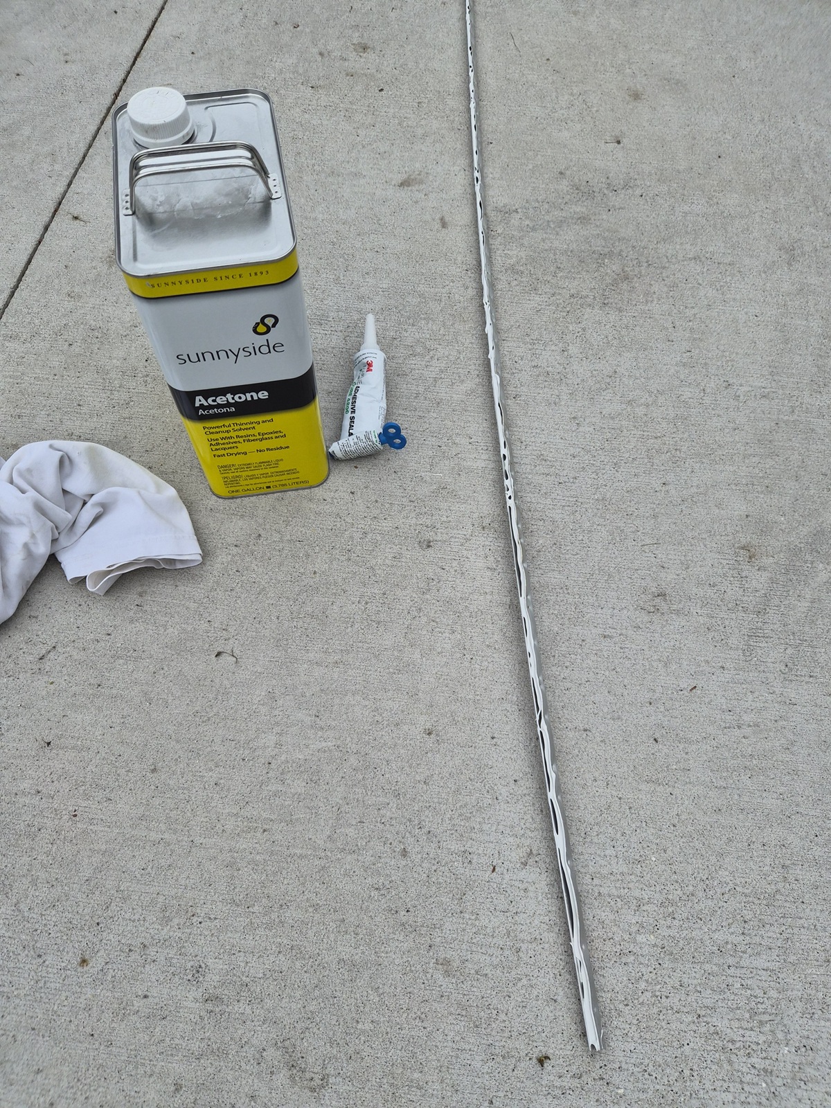
I cleaned each channel with a wire brush followed by a blast of compressed air.


I wiped the pieces down with acetone and applied a bead of 3M 4200 to the inside of each channel. This proved difficult for my aging hands as the 3M 4200 did not easily exit the small tip opening required to squeeze it into the channels.


Used a rubber mallet to aid in fully seating the trim. I applied clamps to ensure it held in place until the 3M 4200 dried. (24 hours)


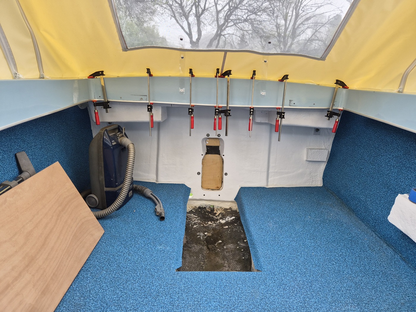
With this installation complete, I was able to move onto mockup of the cabin components.


Original cabin padded trim panels. I'm not certain the black vinyl is original. As noted previously, I plan to recover using Regimental Blue Naugahyde, to match the rest of the boat.


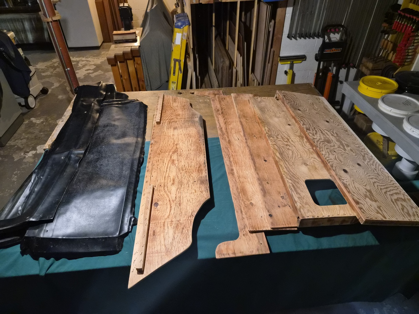
I removed the vinyl and sanded each piece. (including the some of the bunk components)


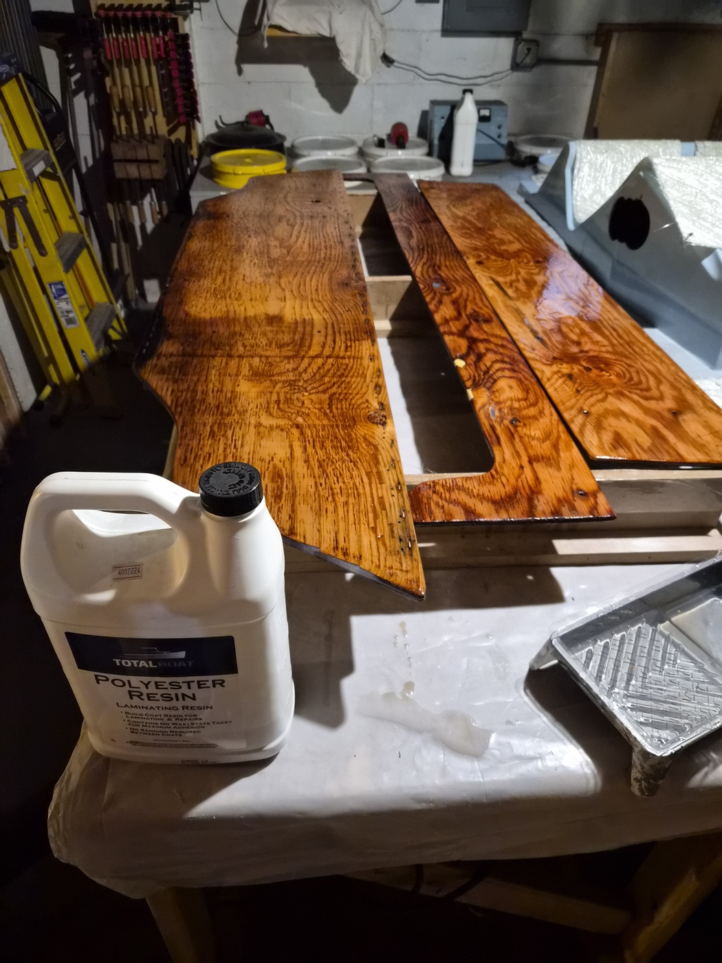
I filled imperfections with polyester structural repair putty and applied a couple coats of polyester laminating resin. As you’ll see, this was done prematurely.


I mounted each piece in their original locations to gauge fit and determined some 'tuning' was required.


I didn't have any 3/8-inch plywood stock on hand, so I ripped strips of wood from the discarded engine cover lid and used a biscuit jointer to attach the strips to the original parts using #0 biscuits. A table saw sled and stop blocks allowed me to fine tune my angled cuts.


Sanded and ready for final fit.


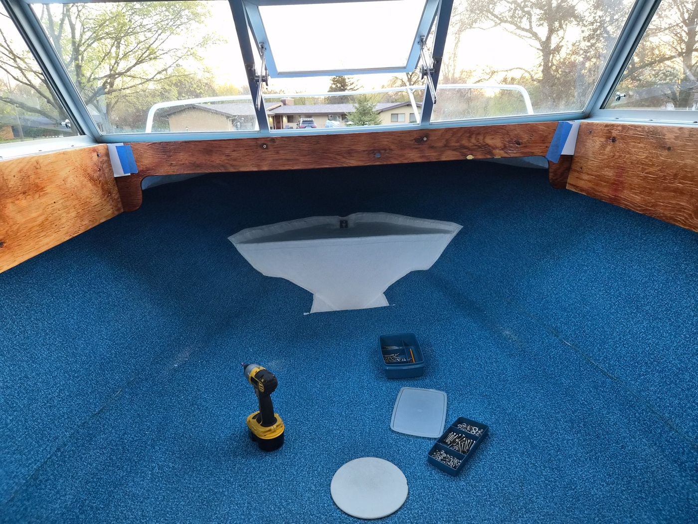
This is a series of pictures showing my final mockup before I disassemble to apply protective finish and foam/vinyl covering.
You can also see I'm well into recreating the cabin walls and bunks. I'll post that experience in the next couple days.


Please Log in or Create an account to join the conversation.

1971 Glasspar Newport Cruiser - Rejuvenation 1 month 1 week ago #149566

Lookin good!
The following user(s) said Thank You: Larsspar

Please Log in or Create an account to join the conversation.

1971 Glasspar Newport Cruiser - Rejuvenation 1 month 3 days ago #149569

  • Larsspar
  • Larsspar's Avatar Topic Author
  • Offline
  • Senior Boarder
  • Senior Boarder
  • Posts: 248
  • Karma: 5
  • Thank you received: 21
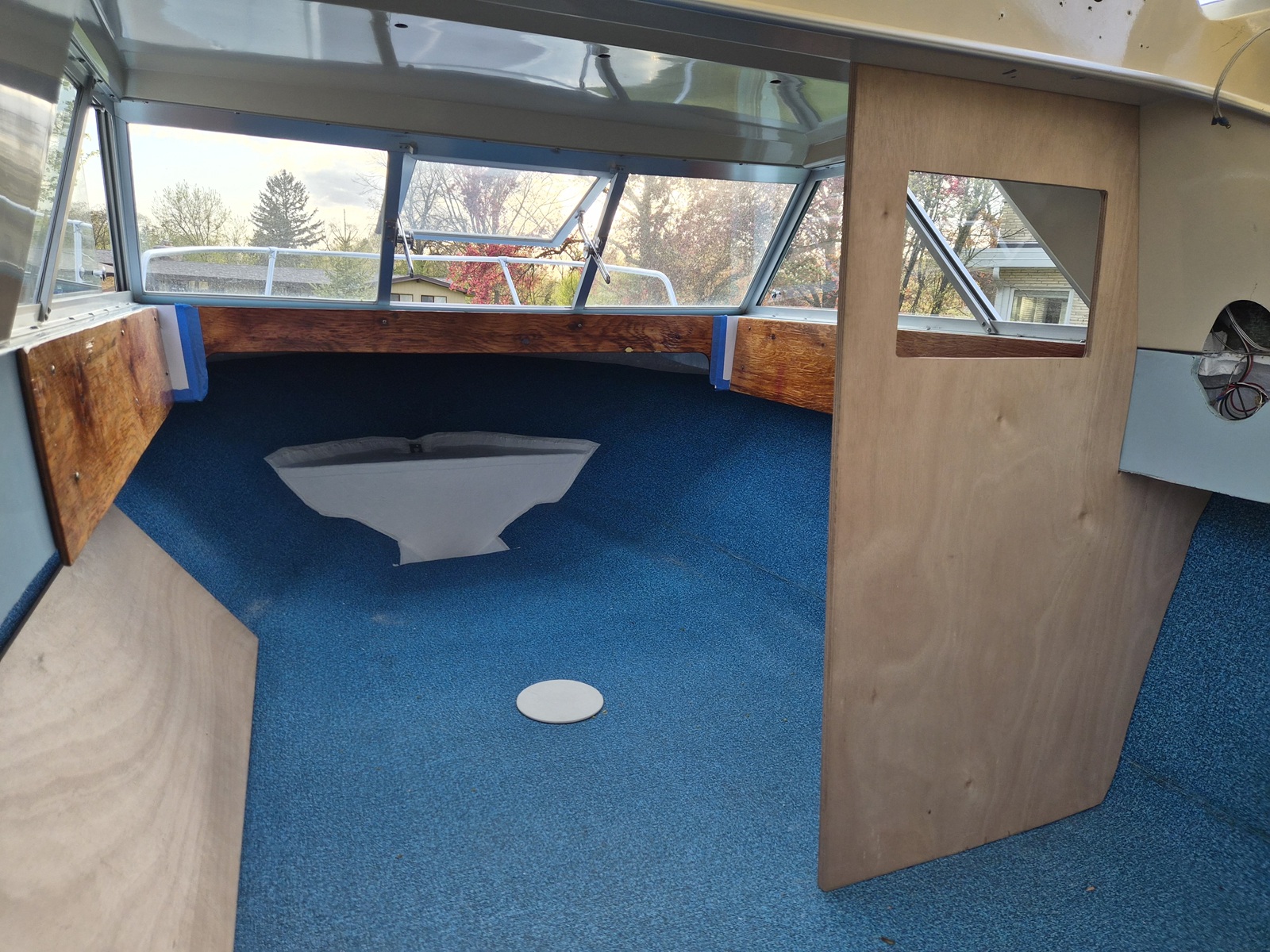
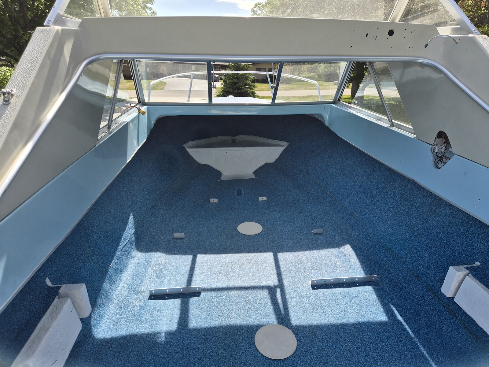
It's taken me a fair amount of time to build out the cabin. I knew I was going to have to replace the original walls, which were scarred and tired, but hoped I could salvage some of the other original components. As I worked through the layout I came to realize modifcations had been made to the original bunks which combined with the work to fiberglass the floor, did not fit together well. The next couple posts will take you through the mock up of the cabin.


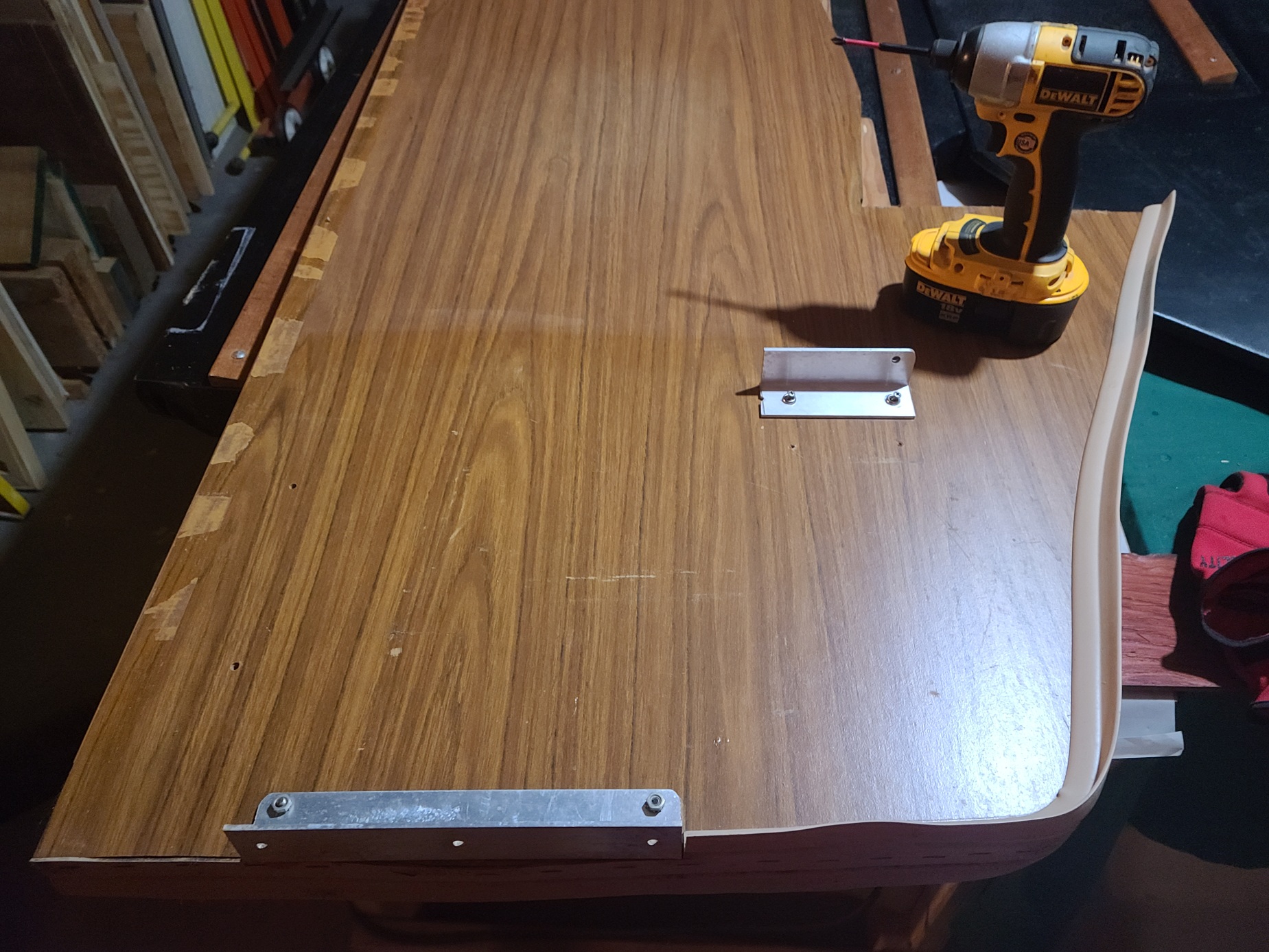
This is the original port side cabin wall and bunk rail. The components are mechanically fastened to hull as opposed to being fiber glassed permanently in place. This hull served more than one boat model.


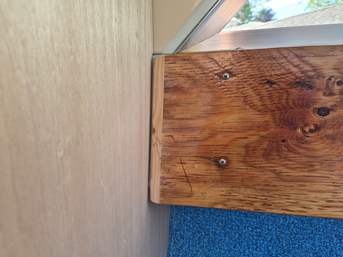
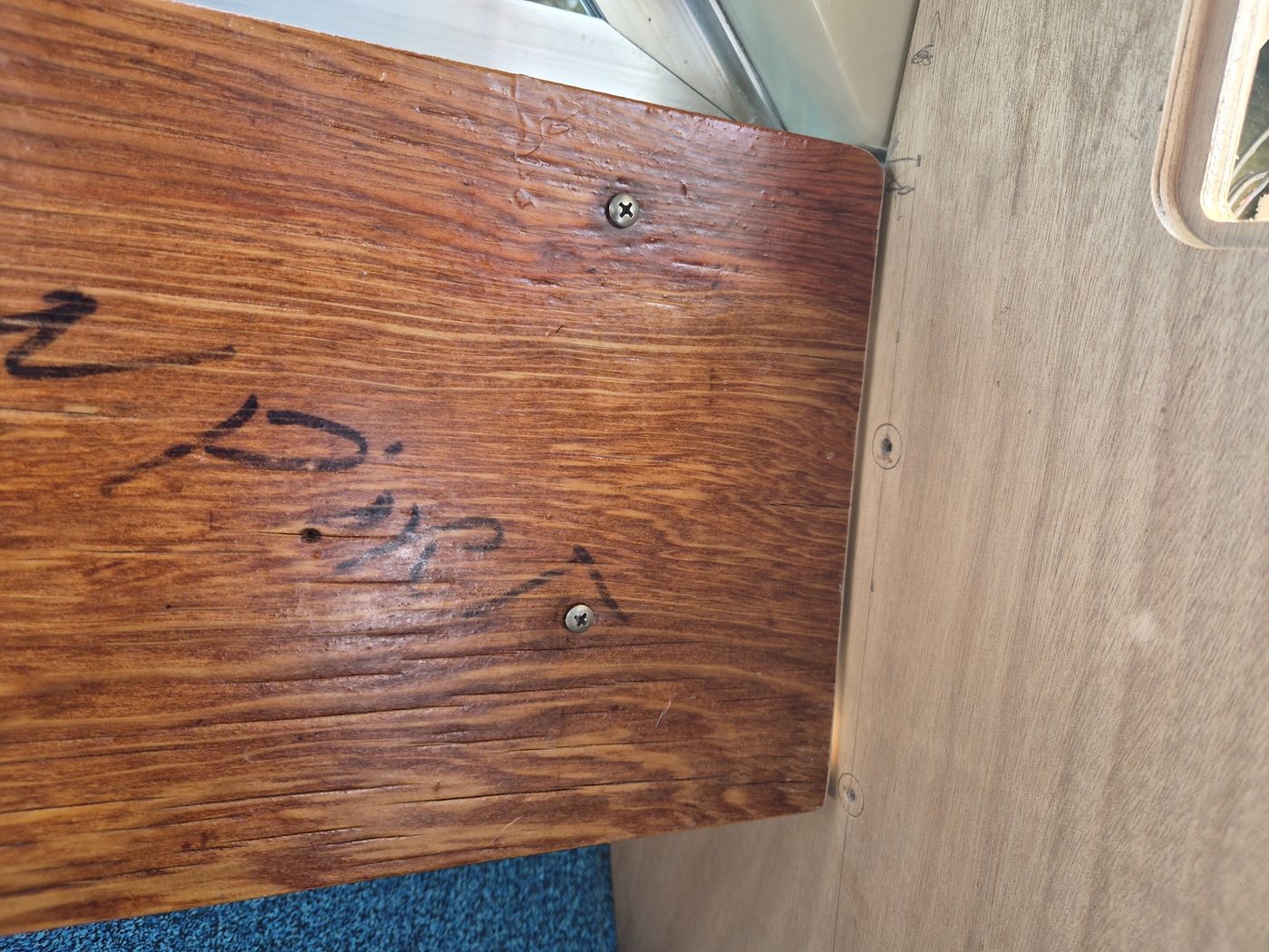
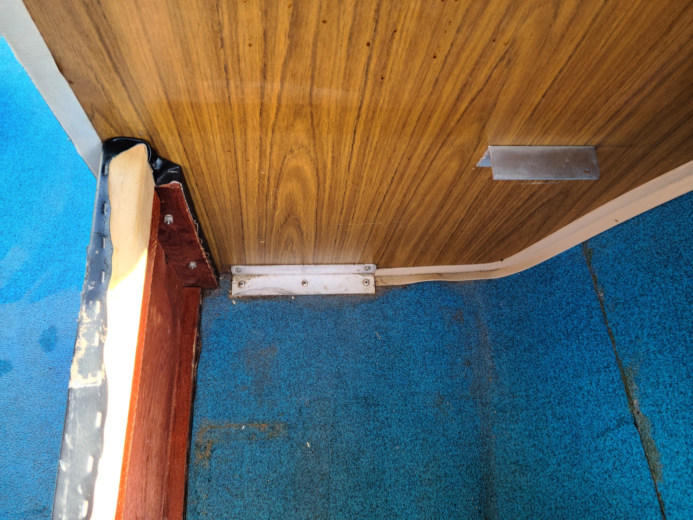
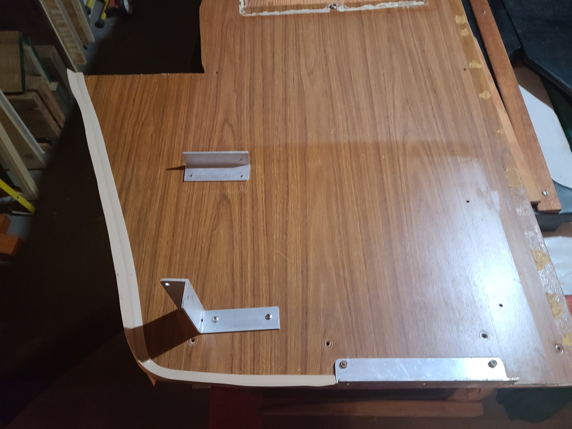
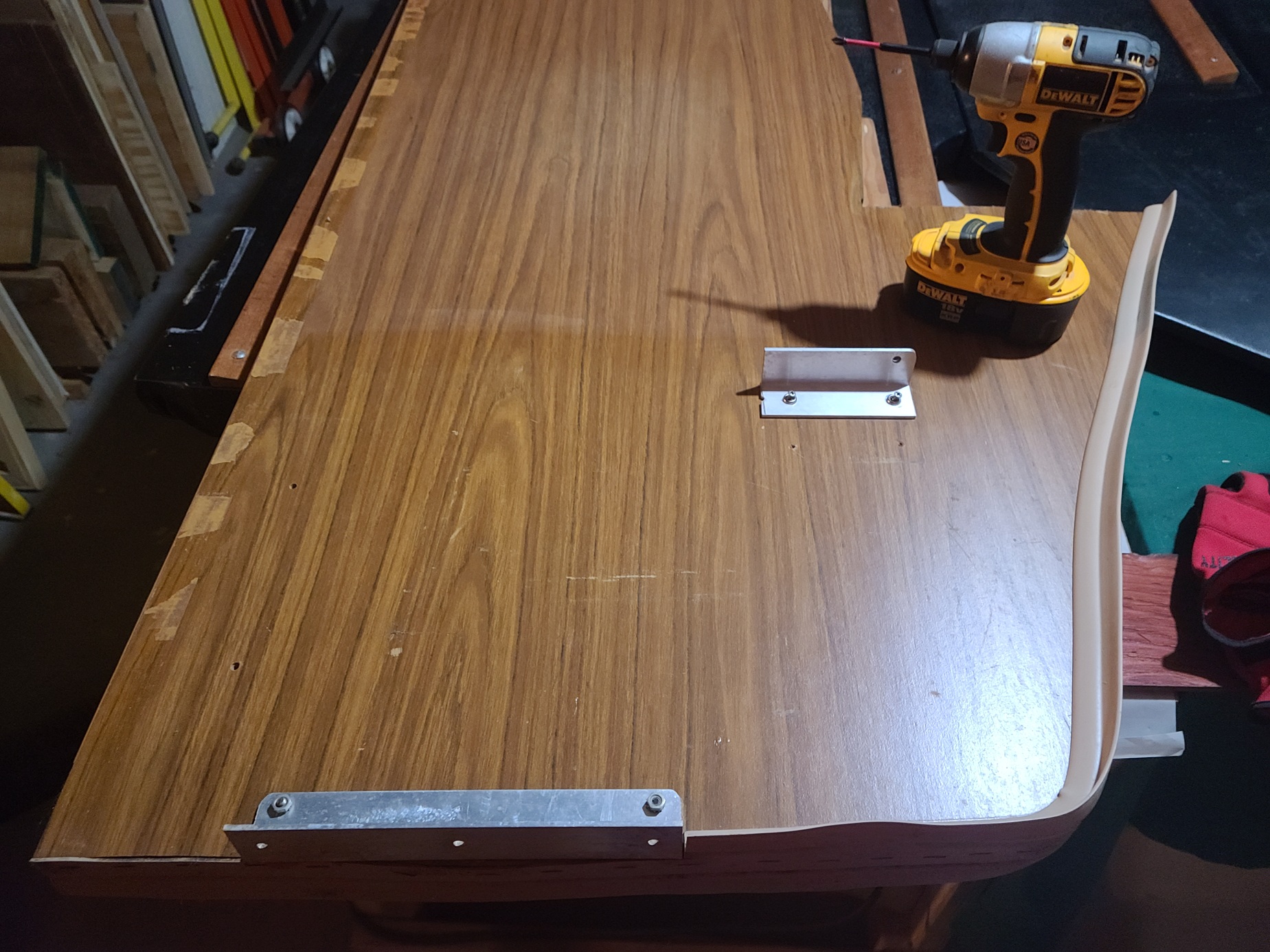
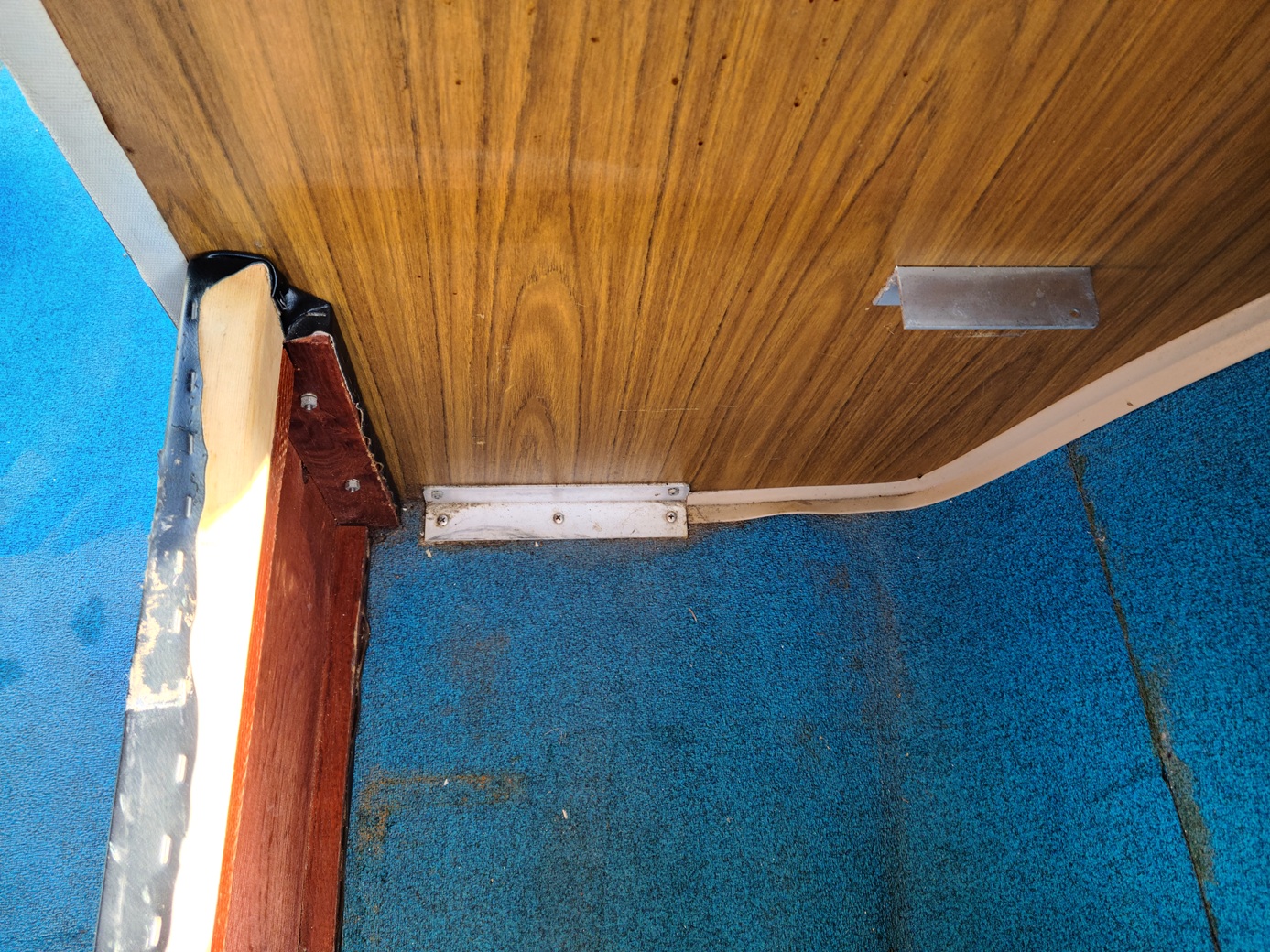
Starboard side original wall. I was comfortable with the aluminum bracket fastening the wall to the boat floor but did not like the other aluminum support brackets. I chose to use wood, when possible, on the replacement.


Port wall uninstalled.


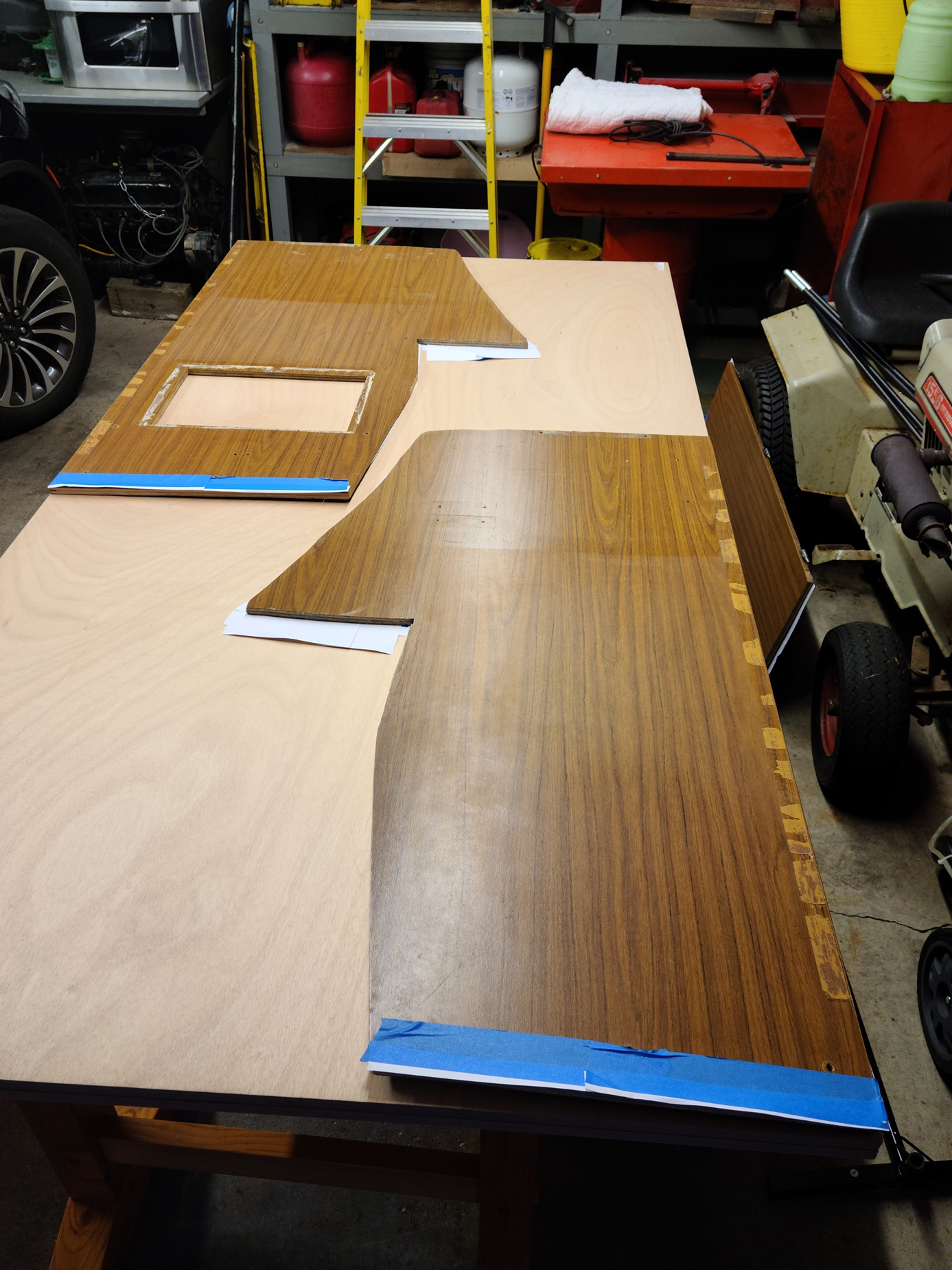
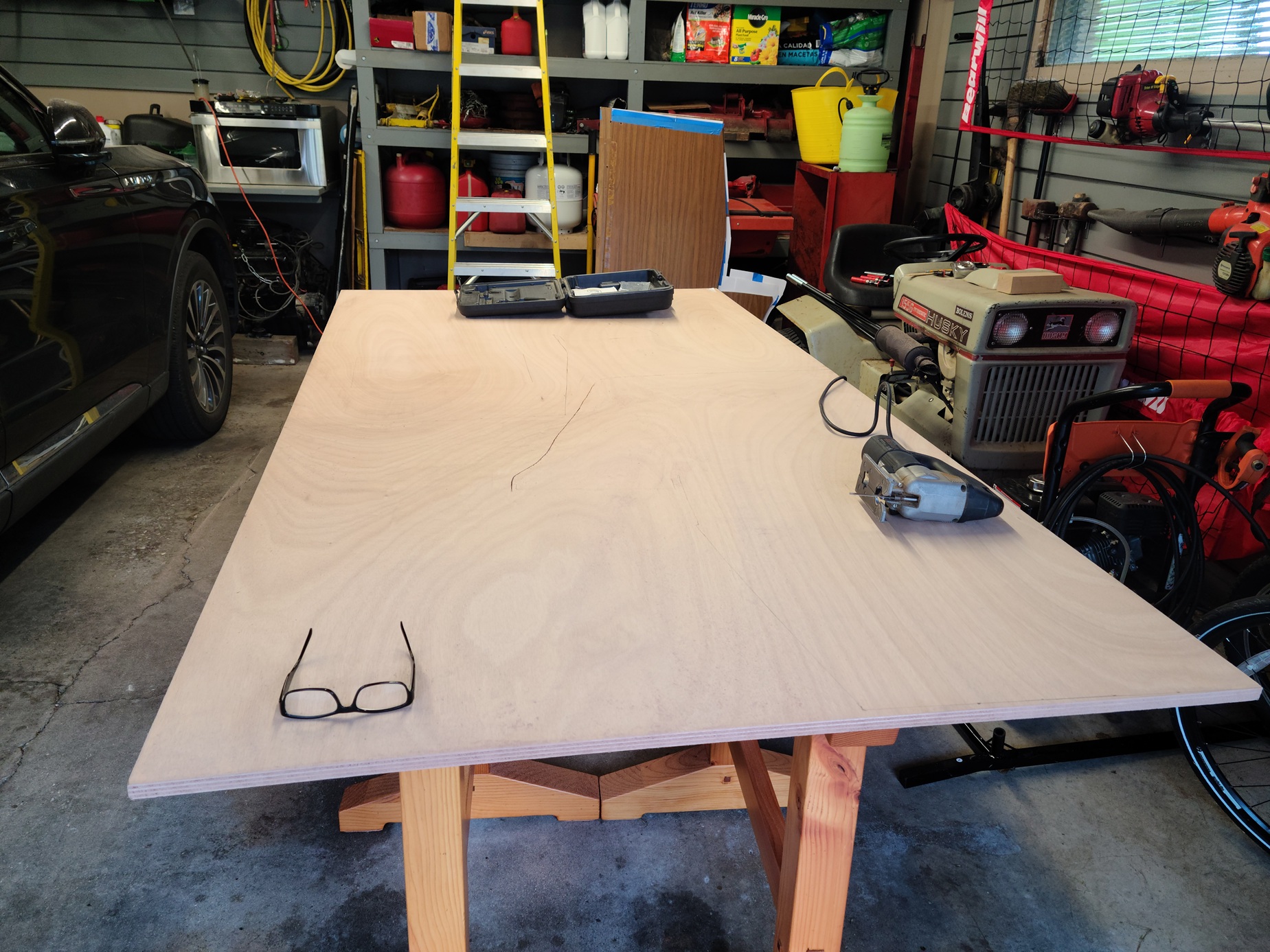
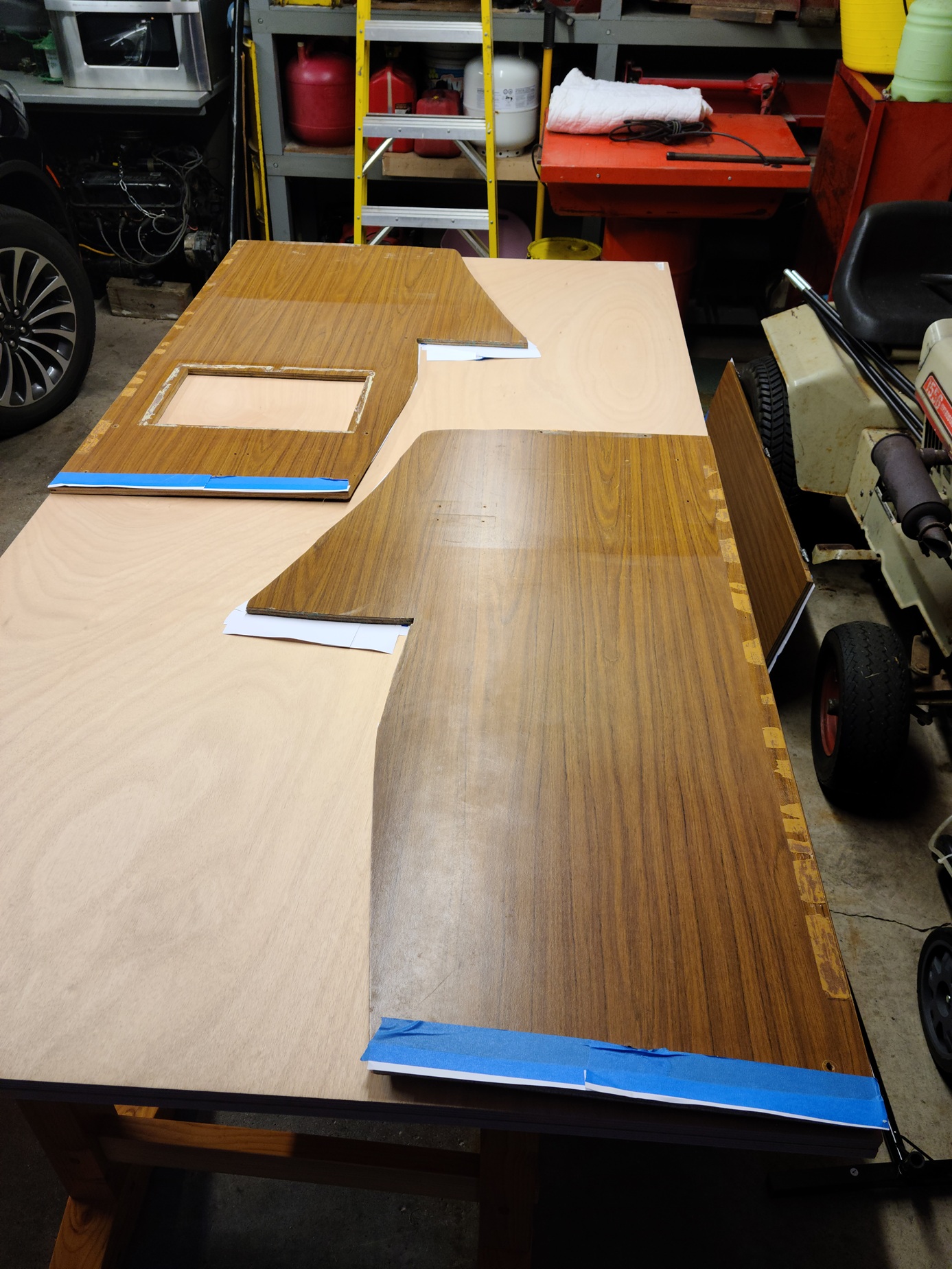
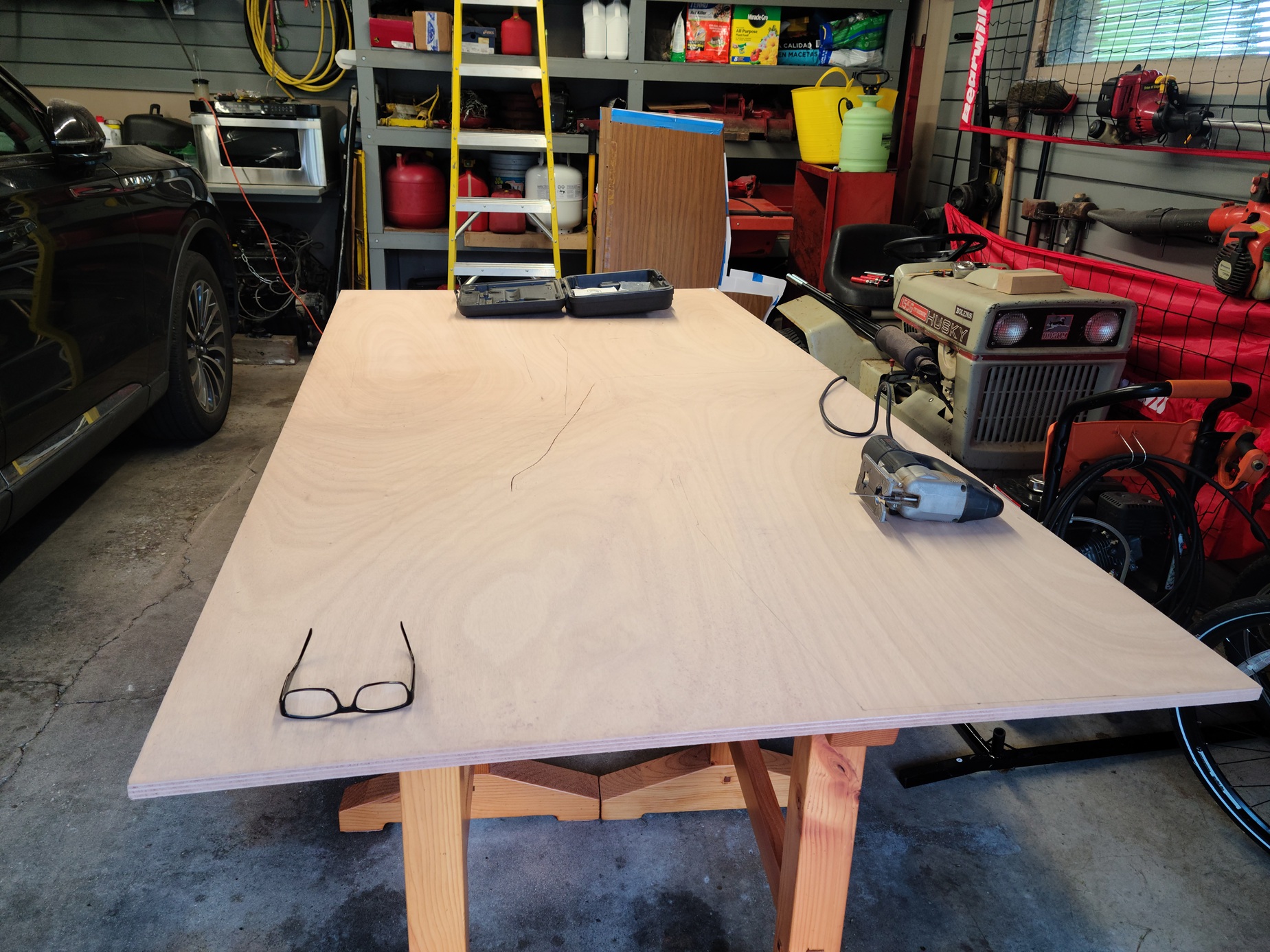
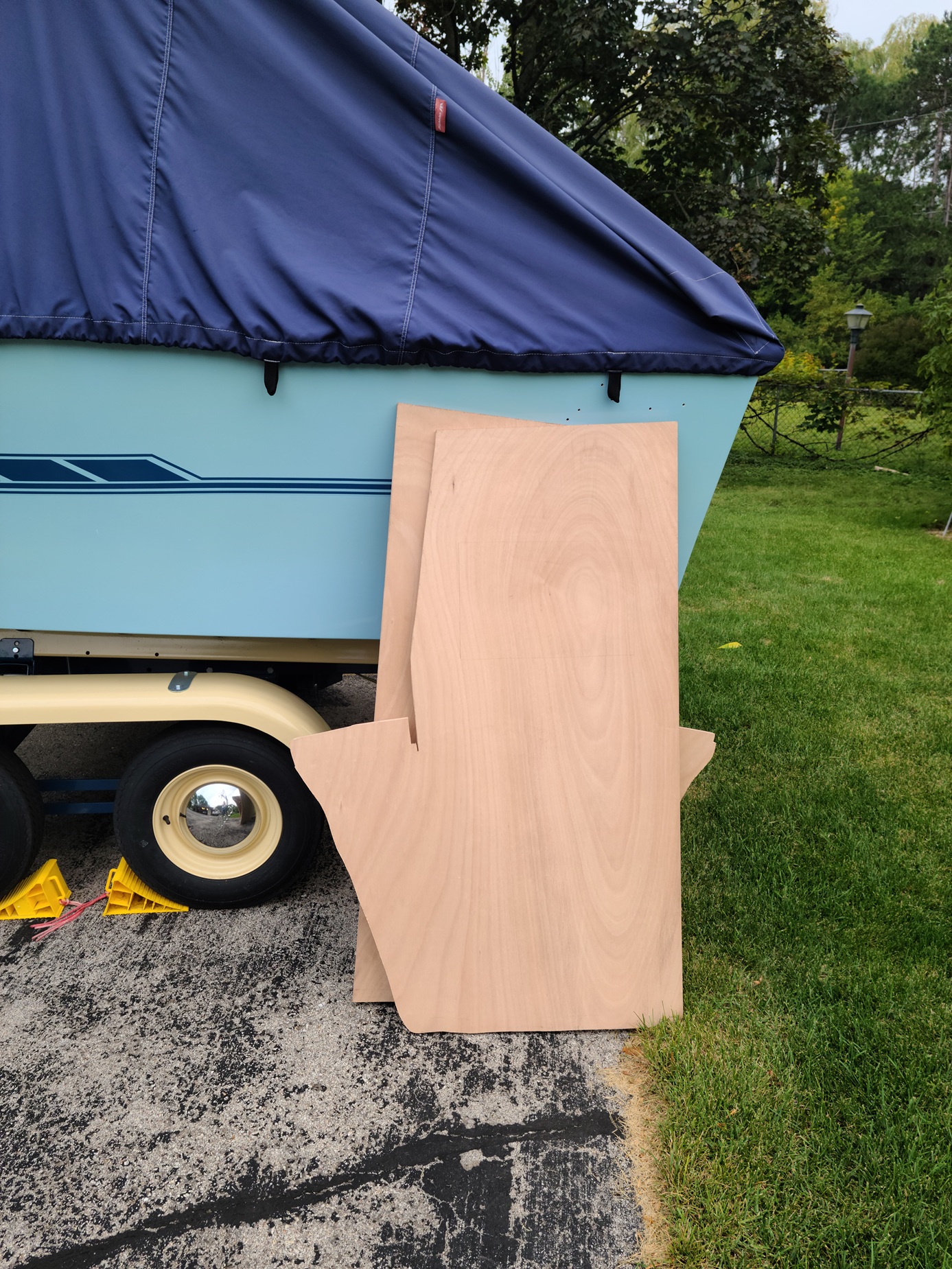
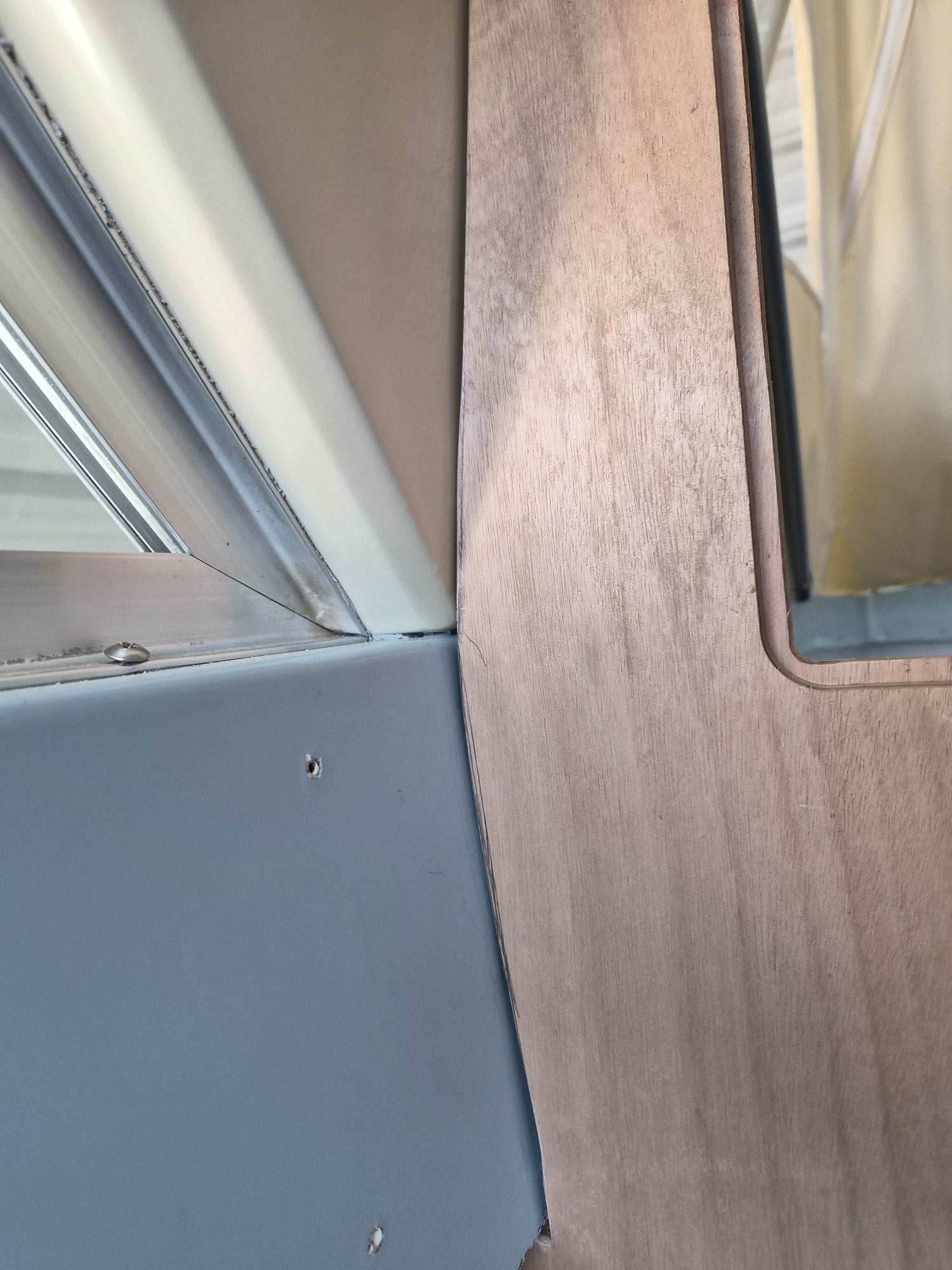
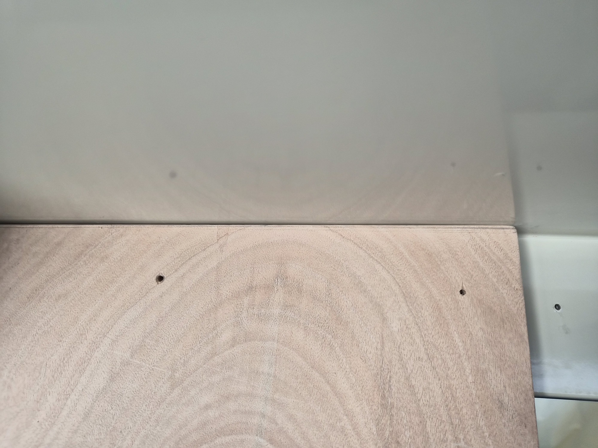
I had to do some trimming of the bottom of the original walls to get them to fit back into the boat because the fiberglass and gelcoat work on the floor shortened the floor to ceiling dimensions. I then used card stock/painters’ tape to template a tighter fit to the hull. Each wall was then laid out and traced onto a sheet of 3/4 inch sheet of marine plywood.


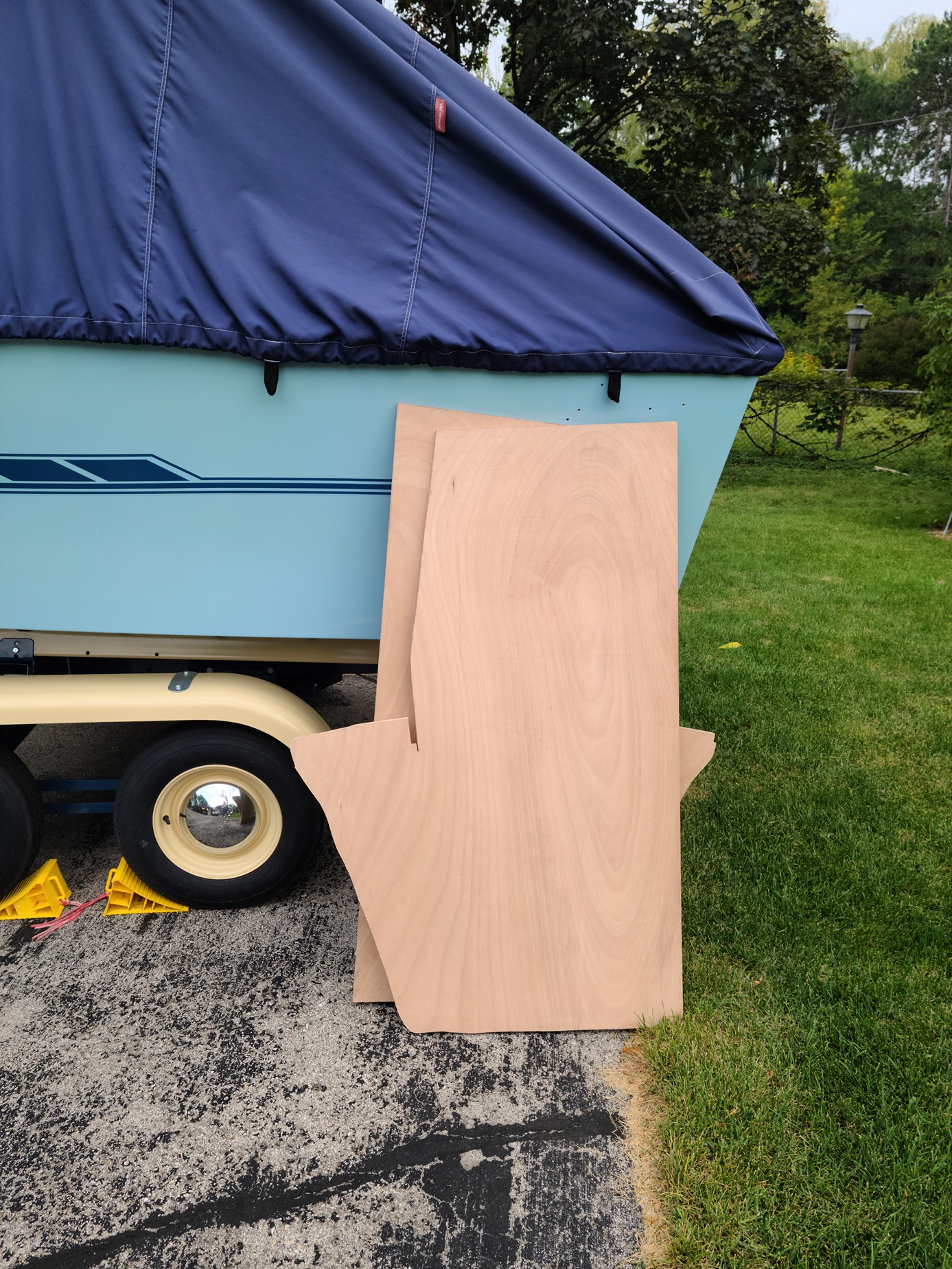
I then used a scroll saw with a fine blade to carefully cut out each wall. I took advantage of the straight edges of the plywood when possible.


My initial new blank walls ready for first test fit. Little did I know I would take each wall in and out of the boat twenty-five times, (sanding/trimming each time) to get the fit I wanted.


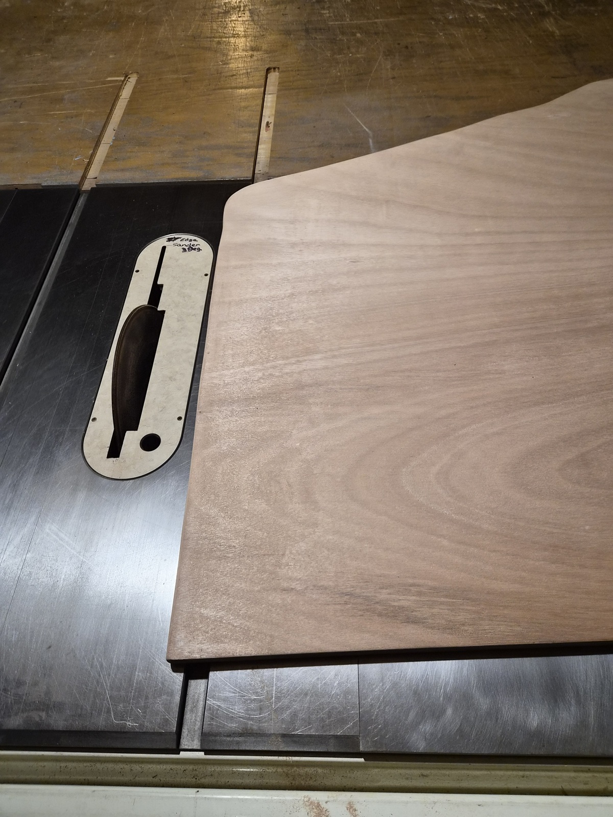
The walls attach to a cabin roof header which slants backward seven degrees. To get the walls to fit the floor properly I had to add a bevel to the bottom of each wall. I did this using a table saw sanding disk which I was able to tilt to get the needed bevel.


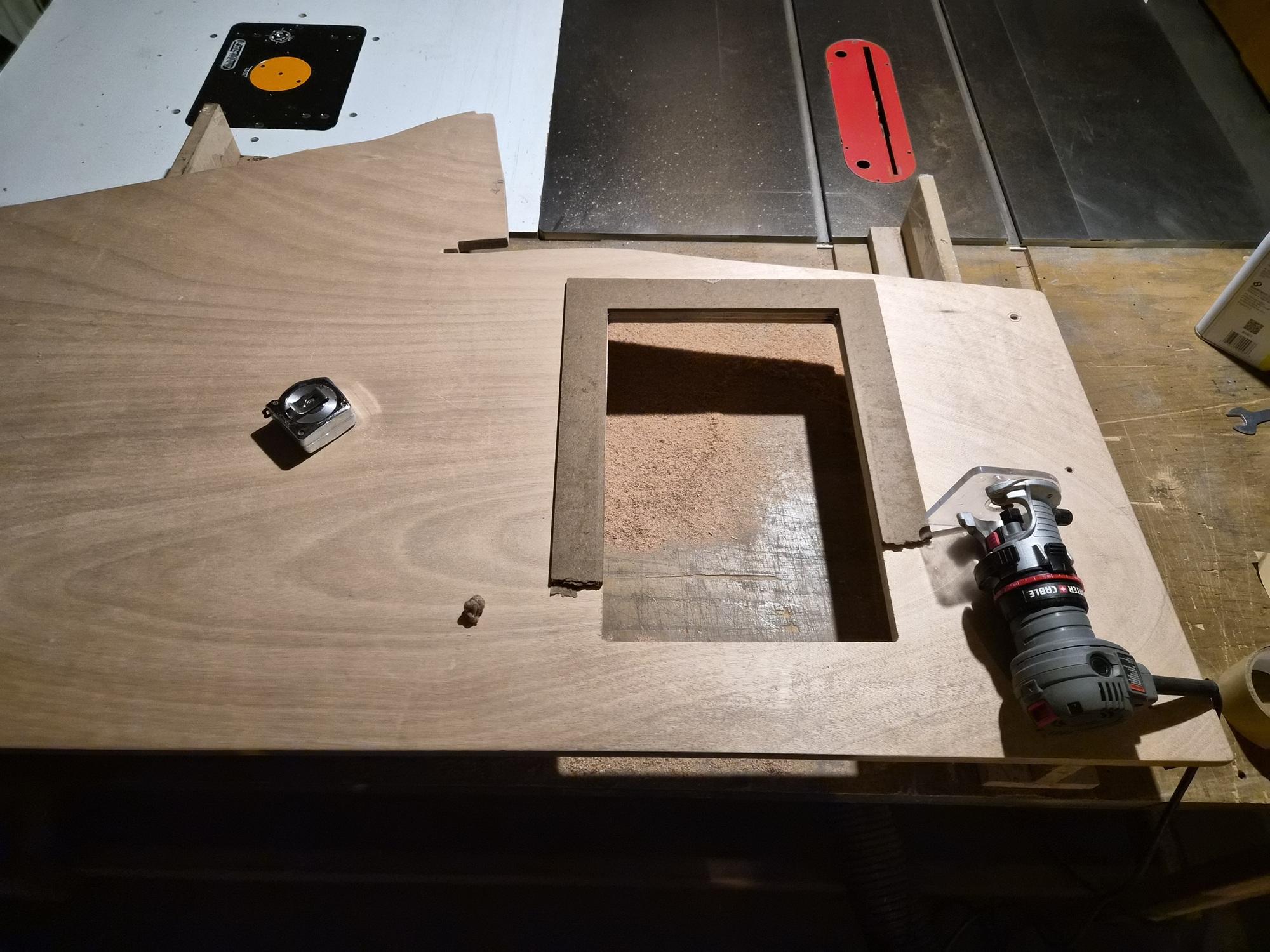
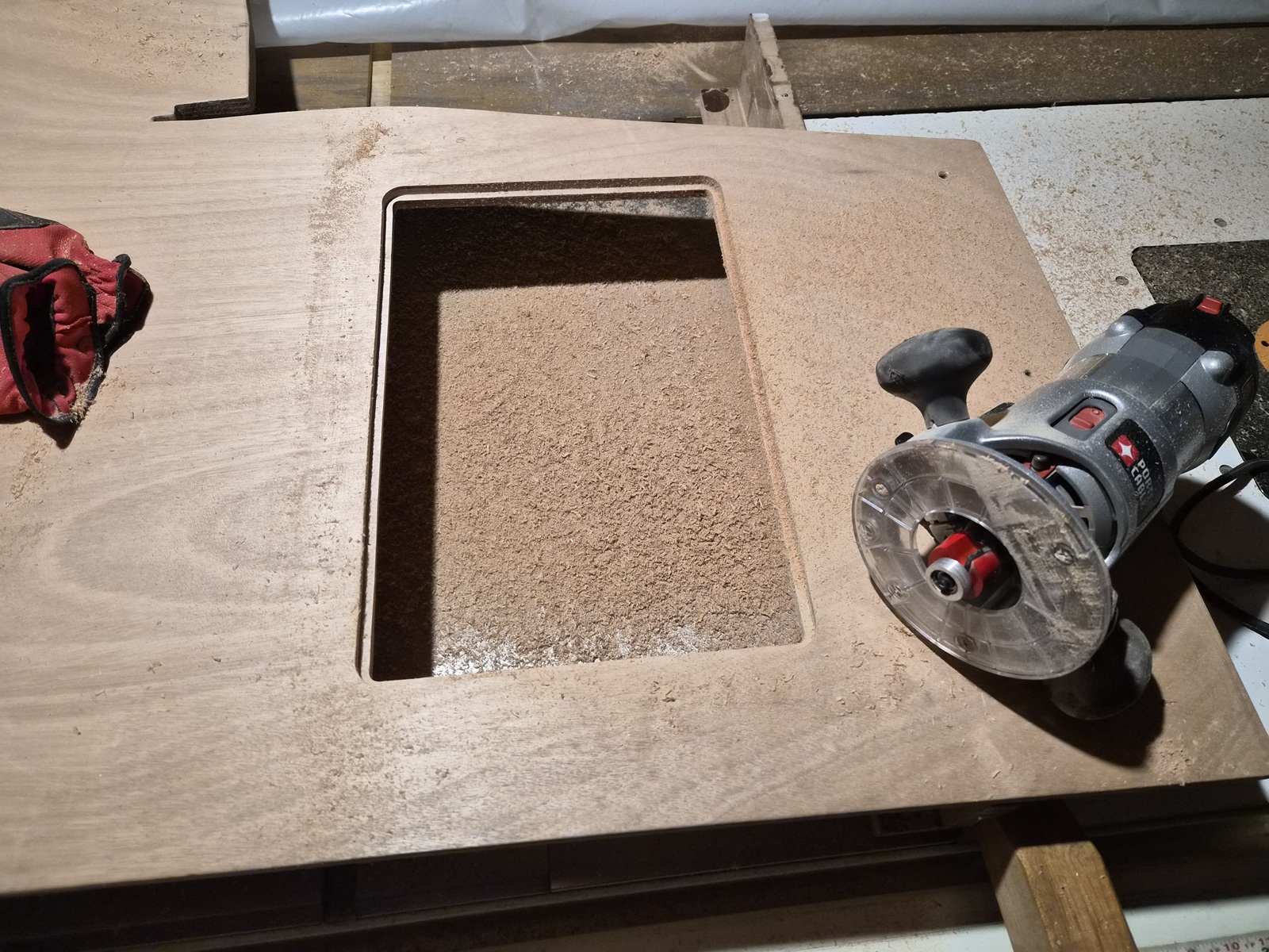
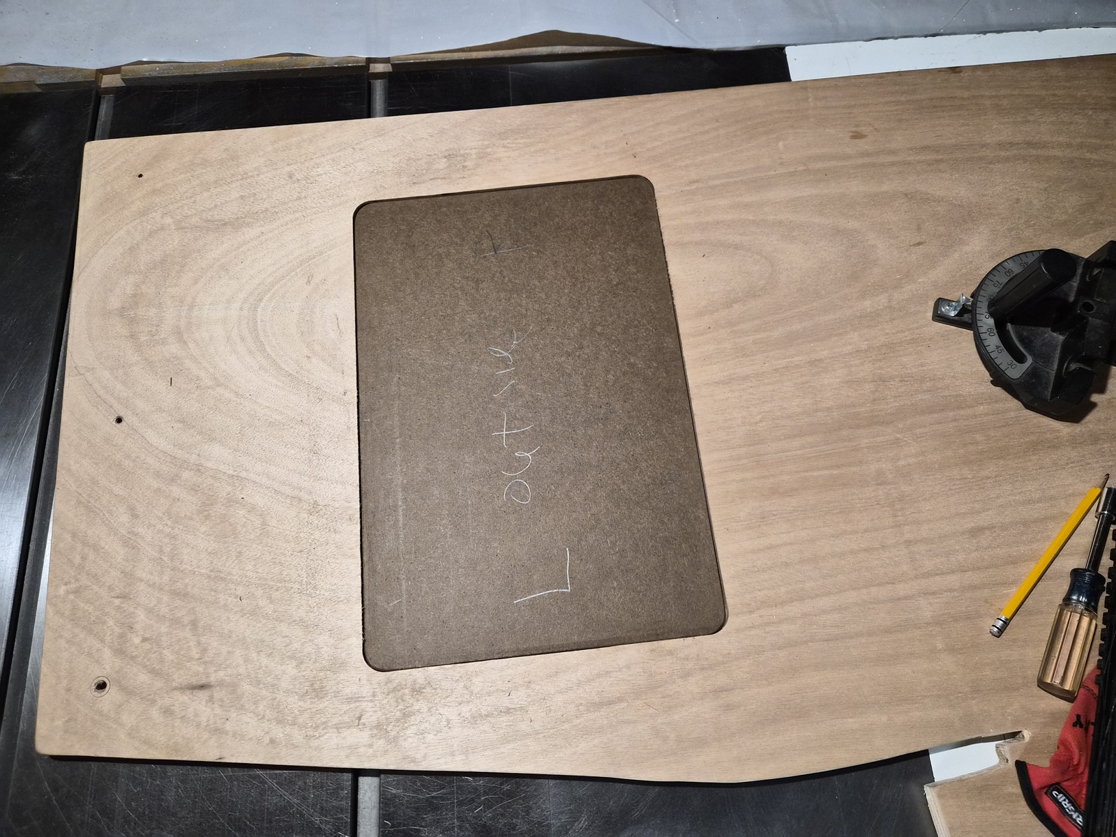
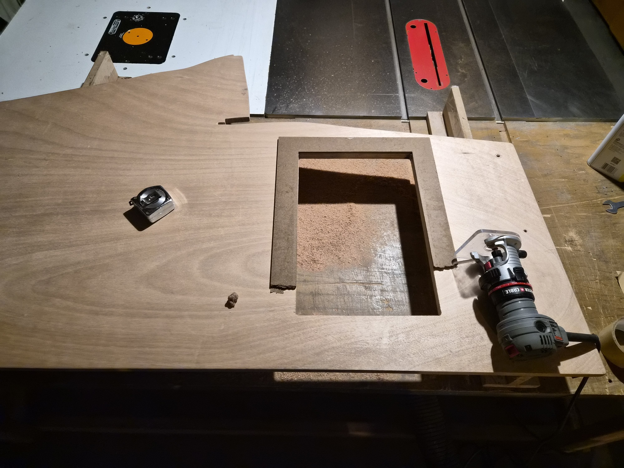
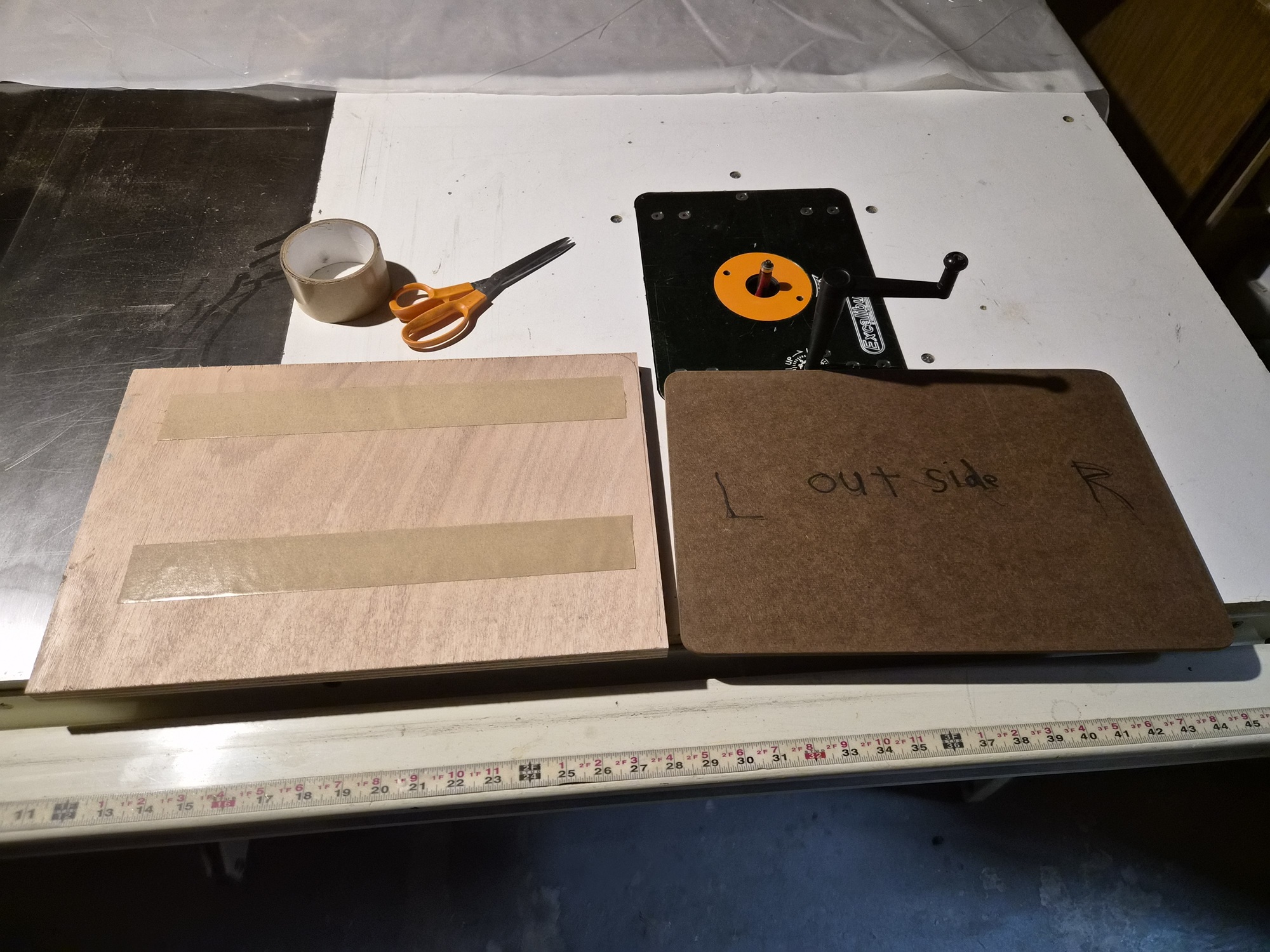
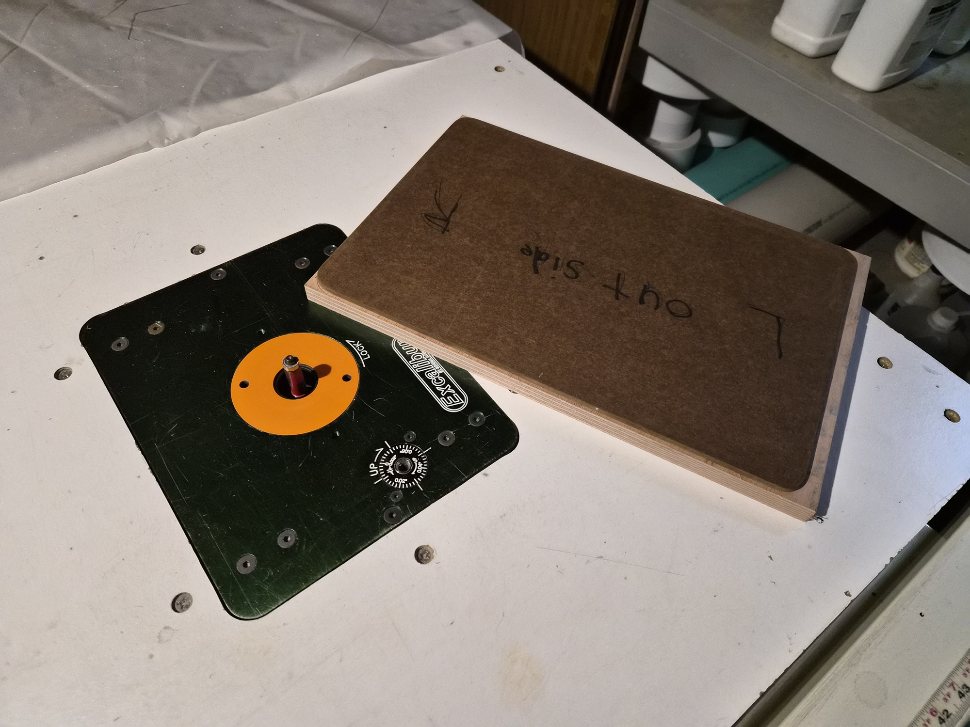
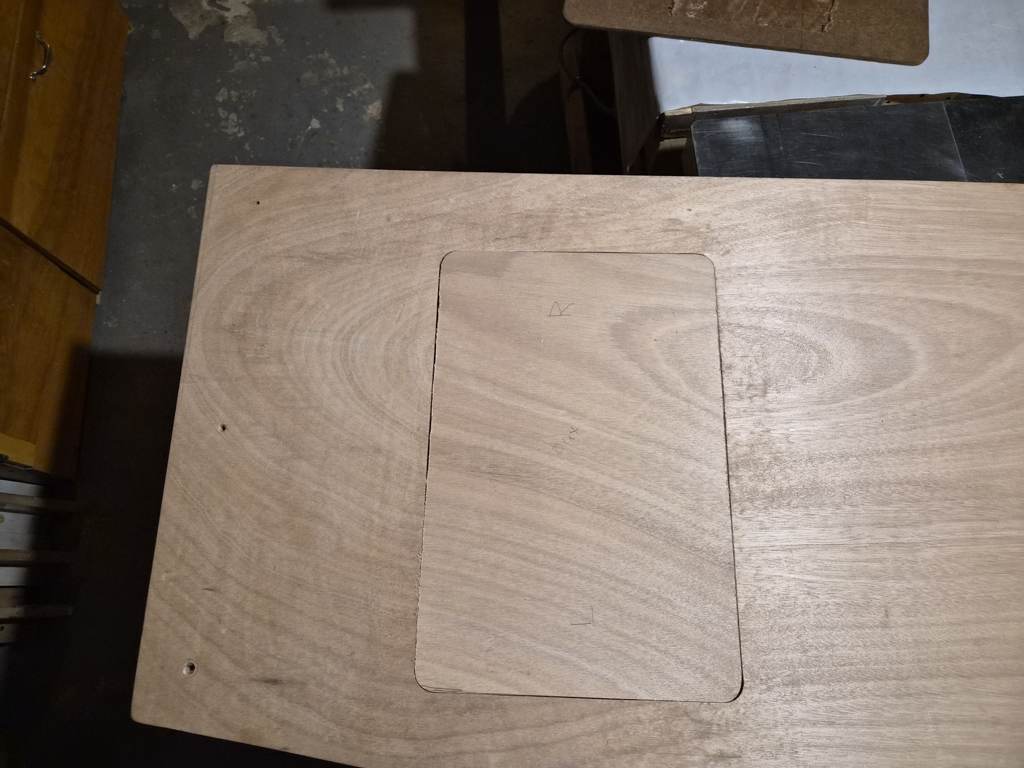
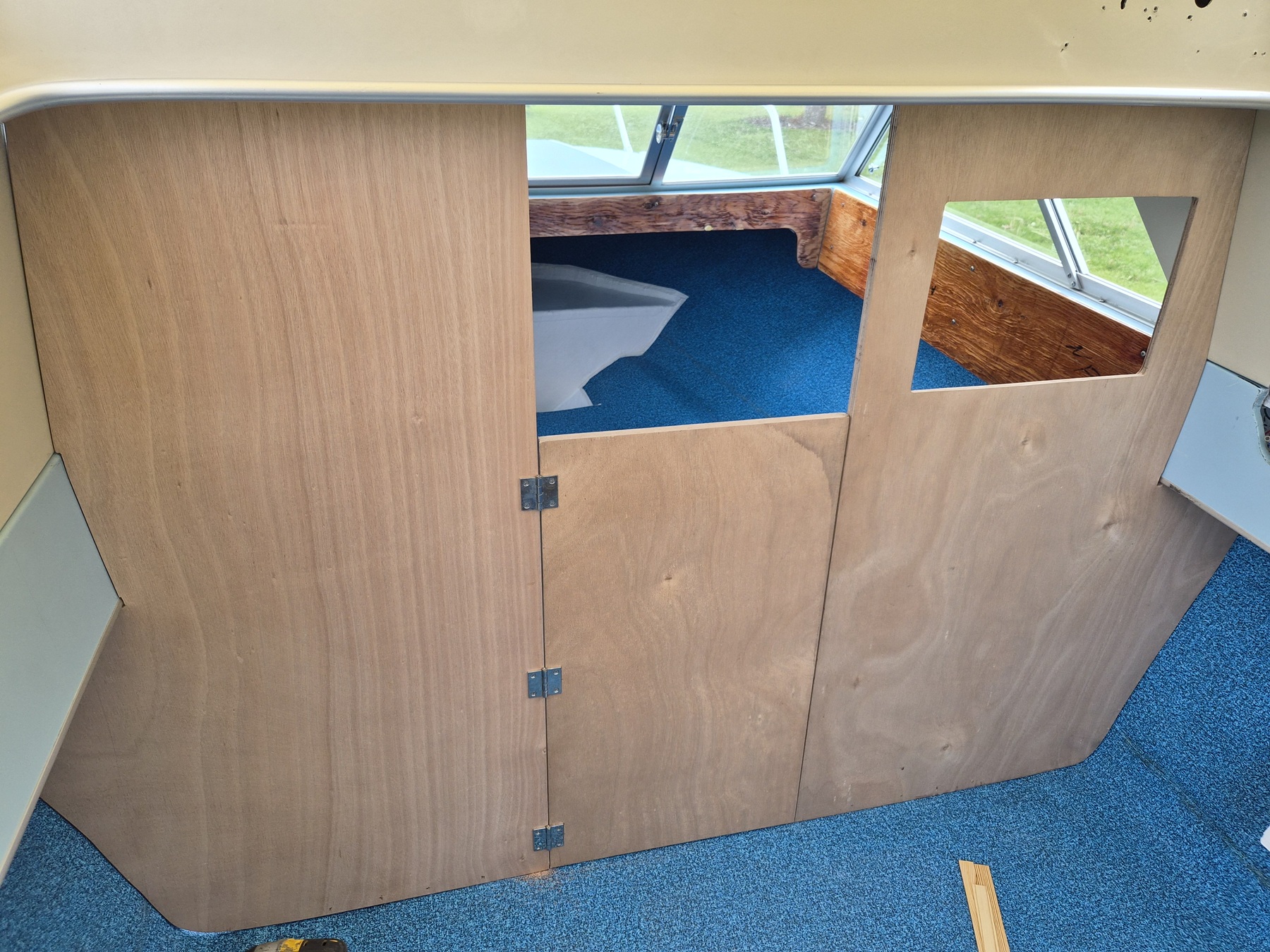
The starboard wall needs an opening to be able to service the components on the back of the helm. The original wall had a crudely cut opening which was covered by a larger piece of wood. I wanted a more refined solution. I started by creating a template out of hardboard. I chose to make a template because I could experiment with different sizes and easily fair the template edges straight to get perfect dimensions. A template also enabled the creation of soft rounded corners via a router bit. Once I created a template I liked, I attached the template to the cabin wall with clamps and traced the desired opening using pencil. The template was removed and a drill and scroll saw used to rough cut to the inside of the opening. The template was then reattached to the cabin wall using two-sided tape. A router with a flush cut bit was used to finish the opening with the router bit bearing riding on the template as a guide. (I didn't remember to take a picture until after I started removing the template)


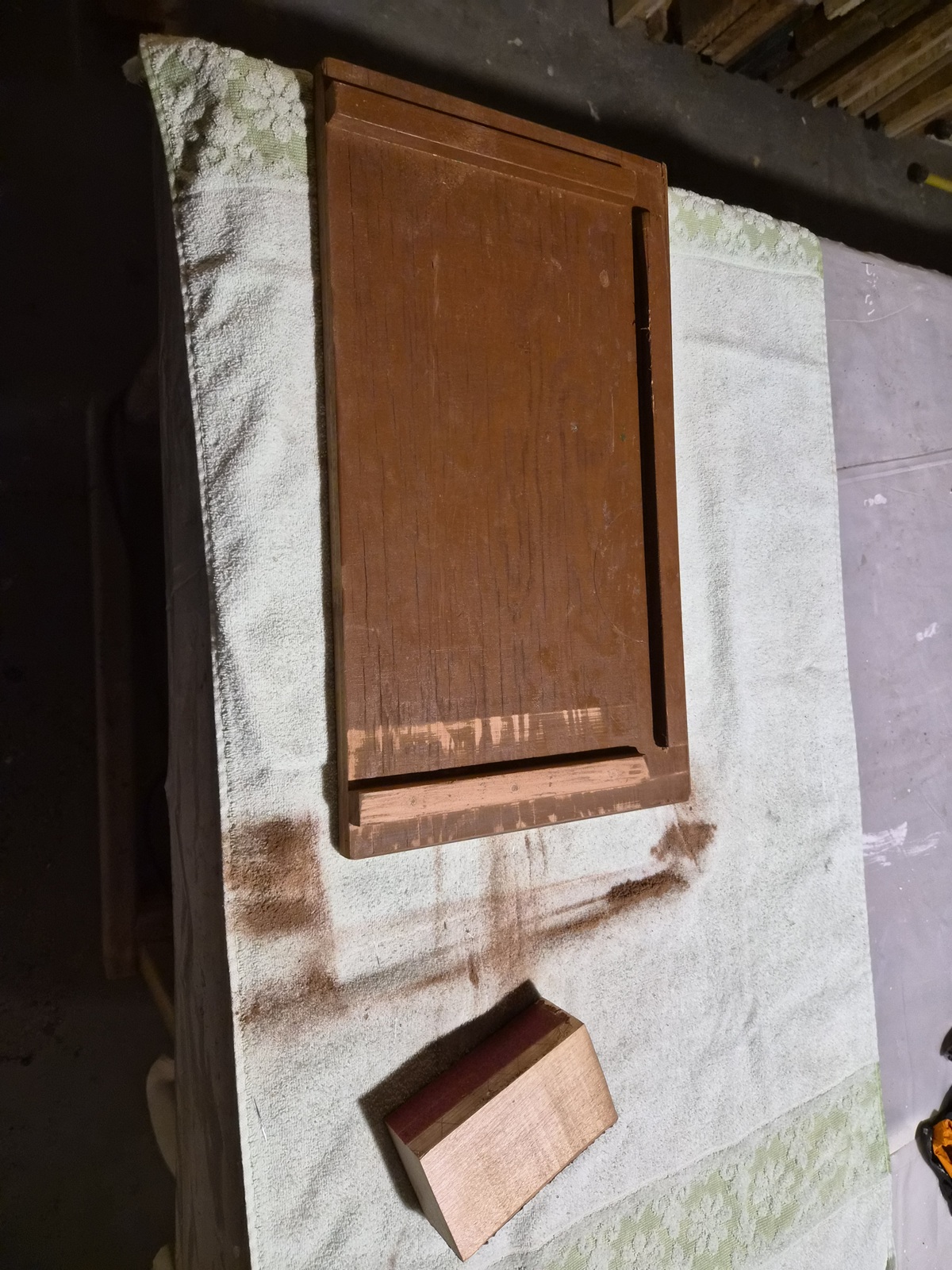
I then used a rabbit router bit to create a 3/8 inch deep by 1/4-inch-wide rabbit in the wall. This allowed me to recess the cover/door into the wall.


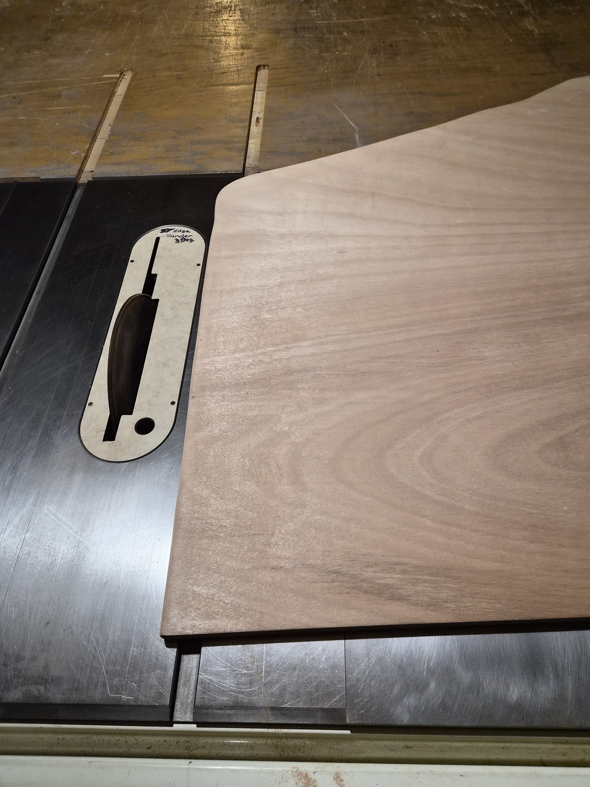
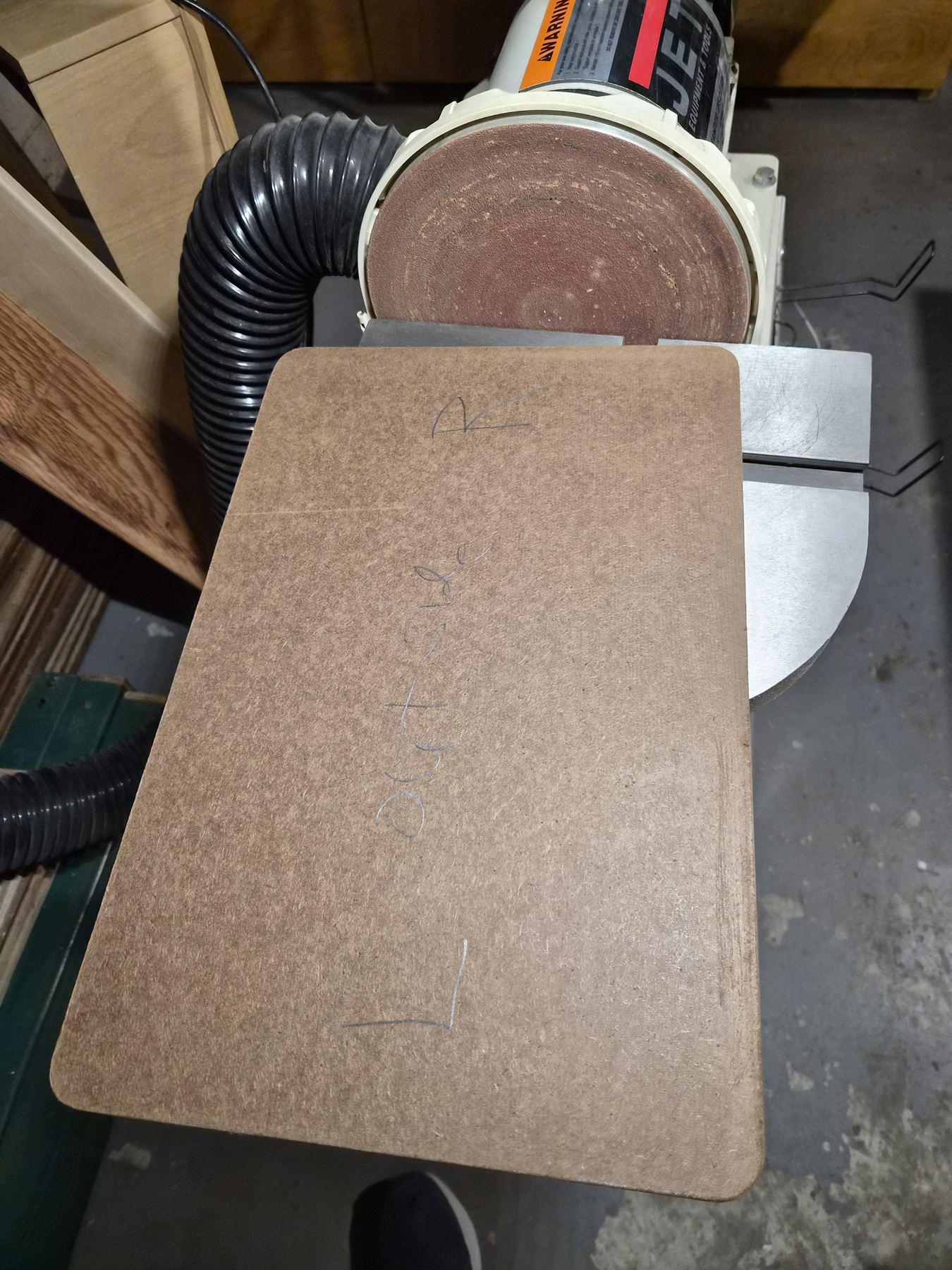
To create the door, I started by making another template which fit the larger portion of the wall opening. I had to use this stationary sanding disk to carefully round the template corners to match the wall opening.


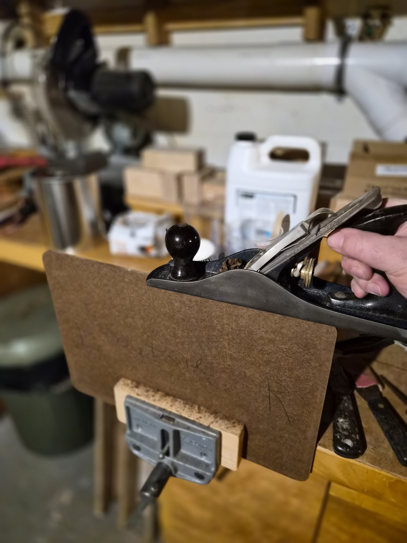
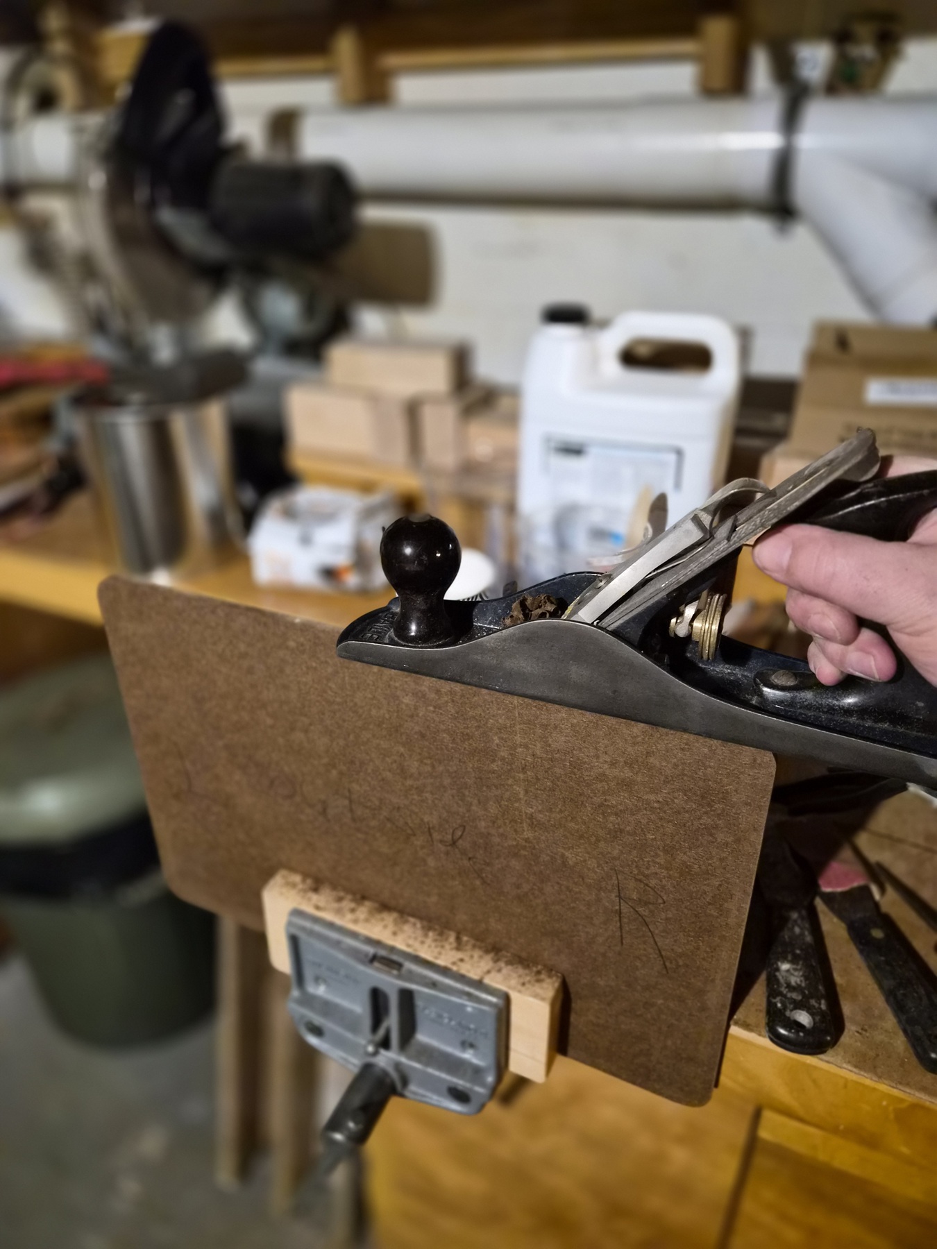
Example of how a template allows me to create very straight edges using a plane.


By using a plane, I was able to sneak up on a good fit.


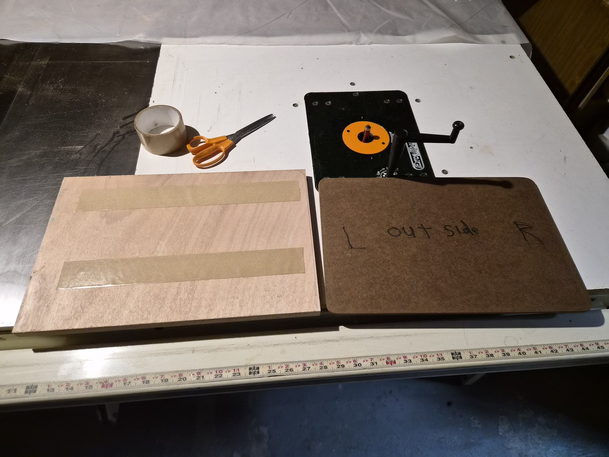
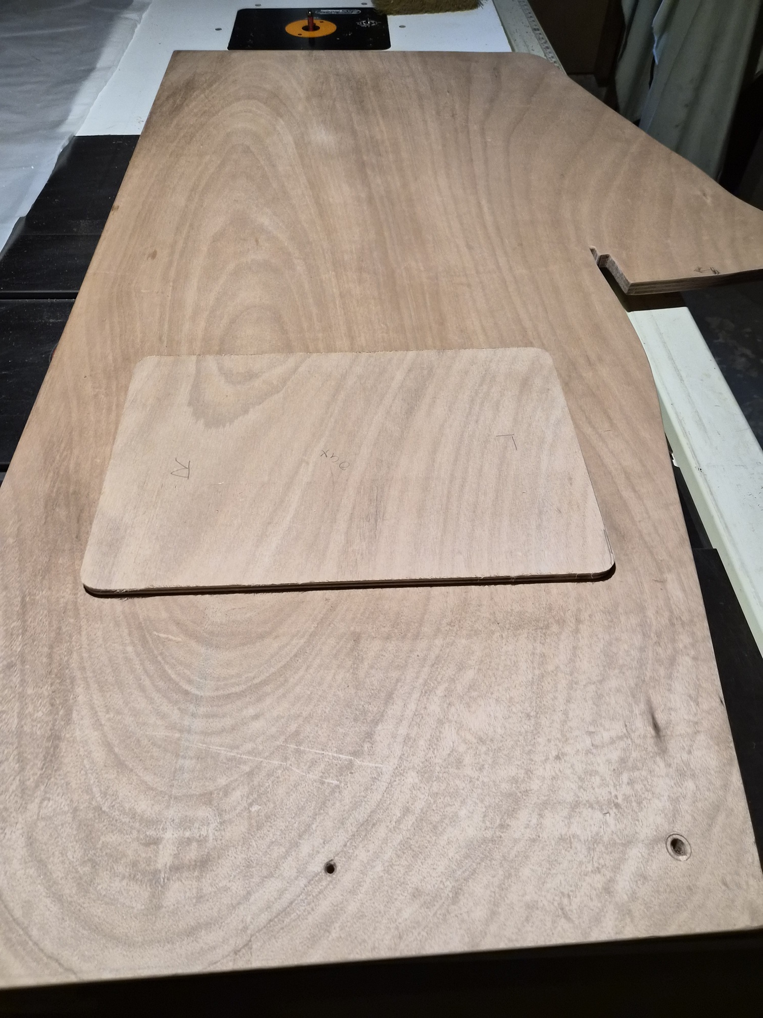
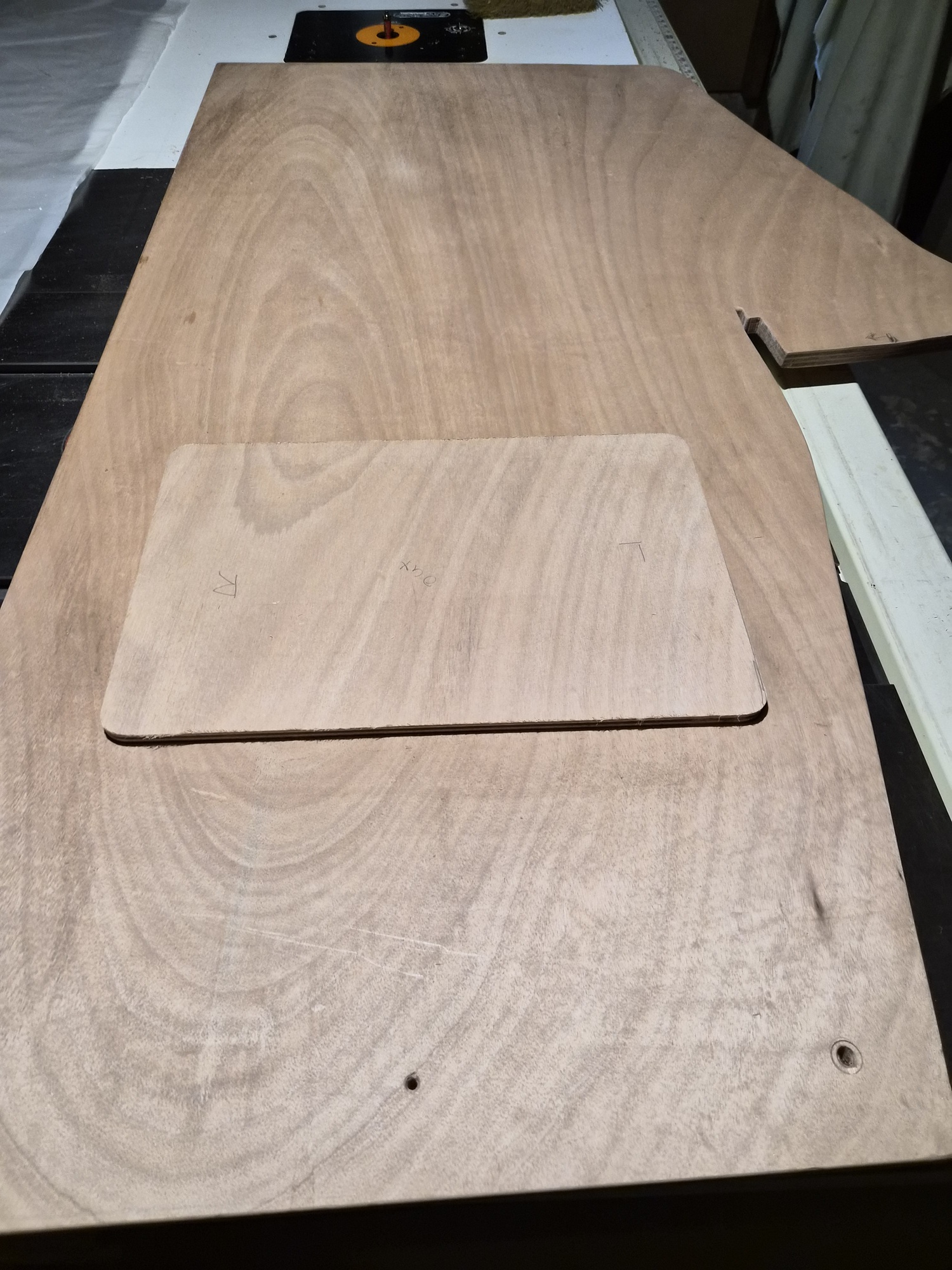
I cut a blank out of 3/4-inch marine plywood slightly larger than the wall opening and attached the template to the blank with two-sided tape.


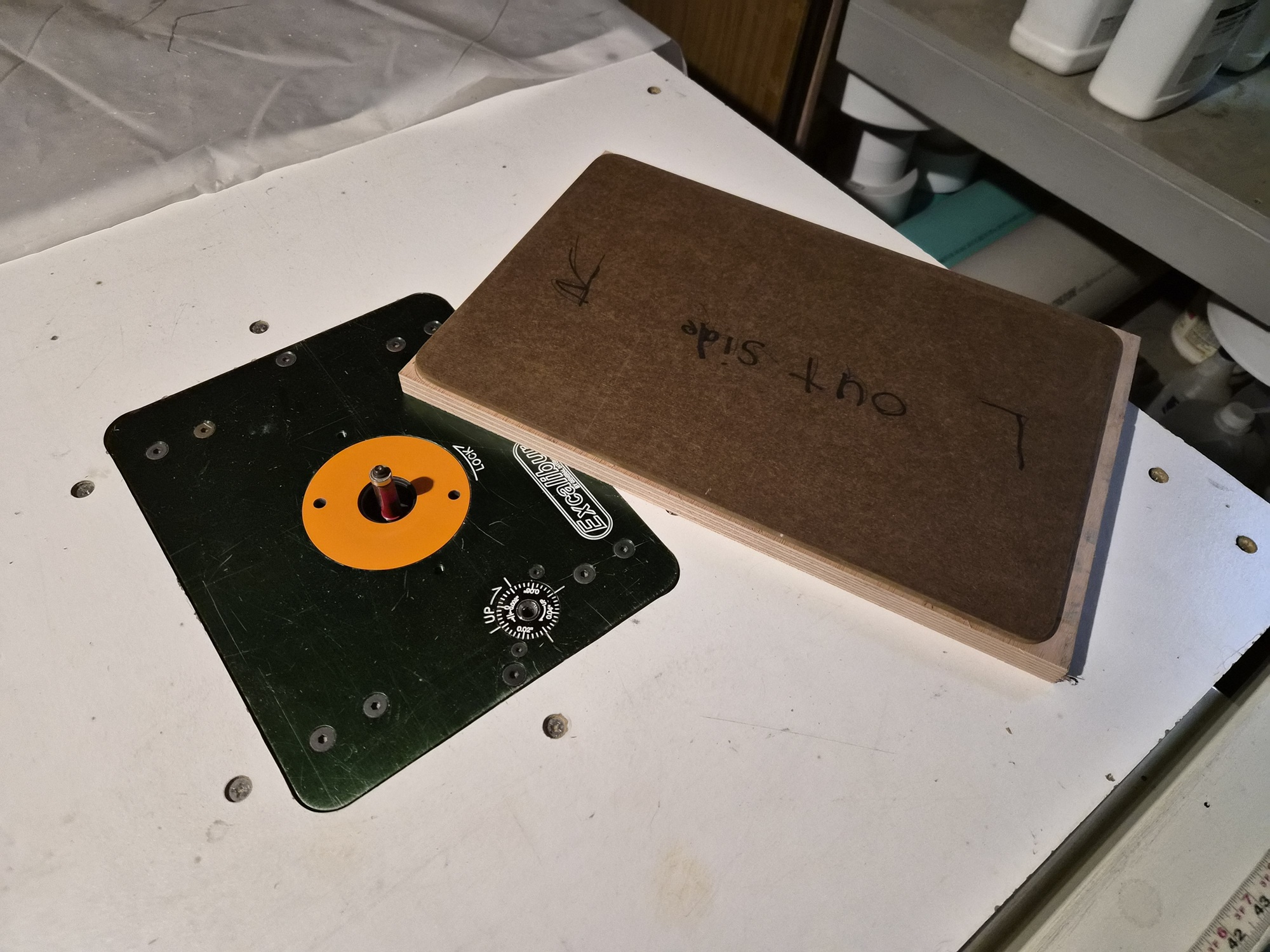
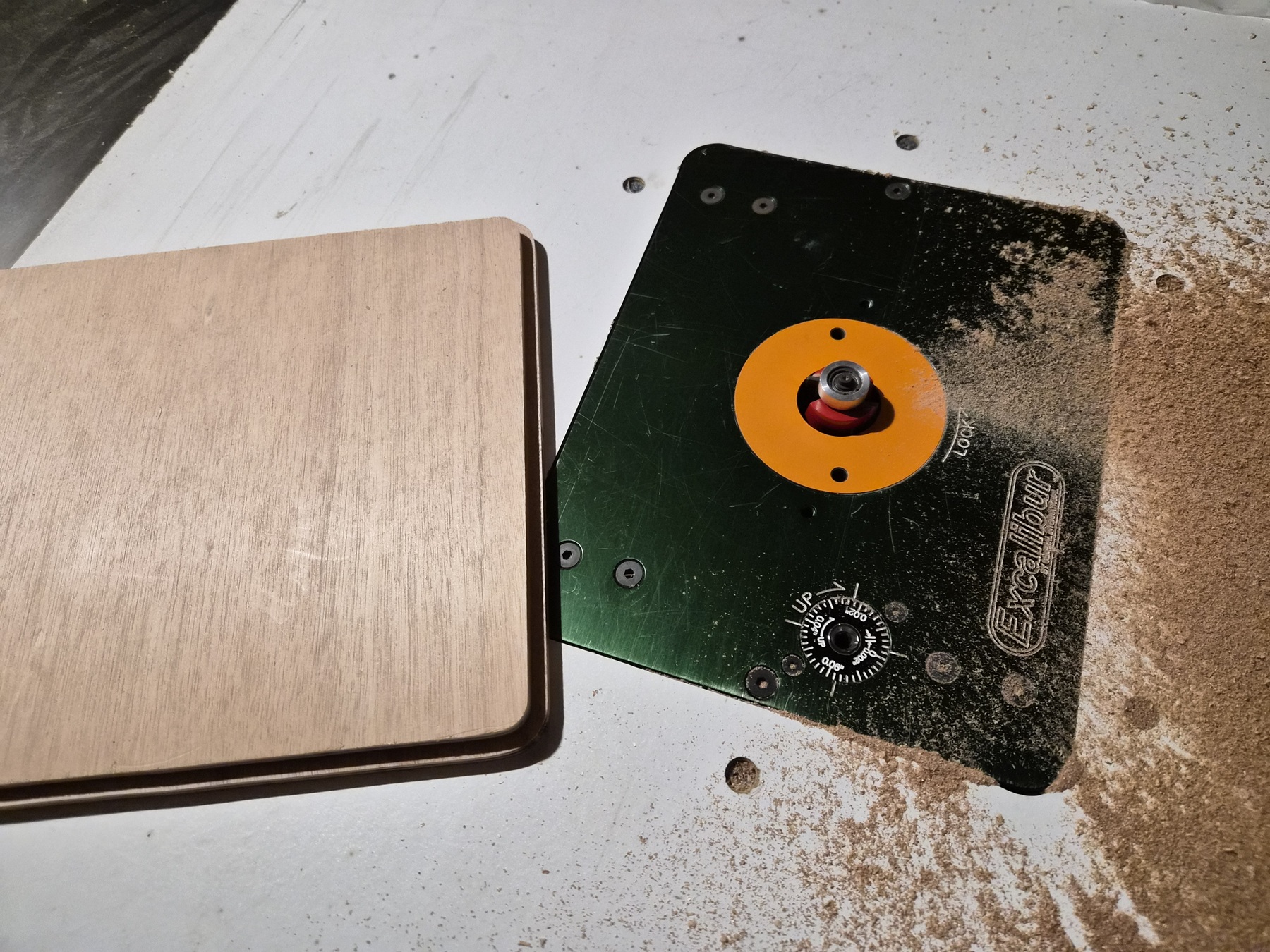
I installed the flush cut router bit in my router table and routed the blank to match the template.


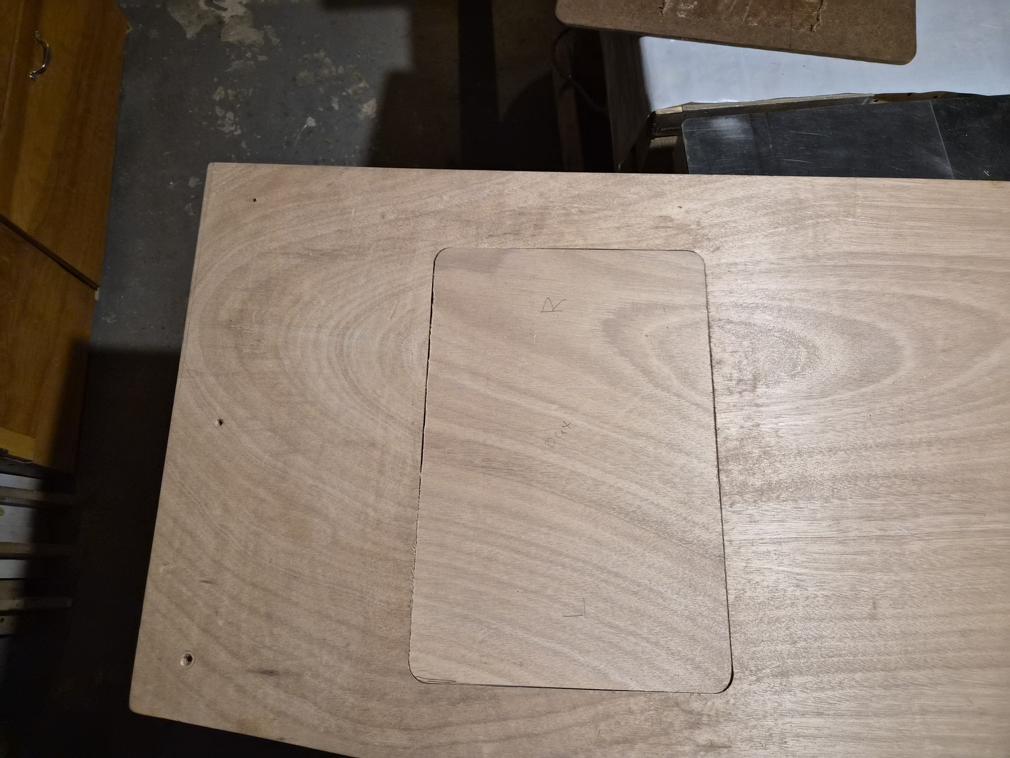
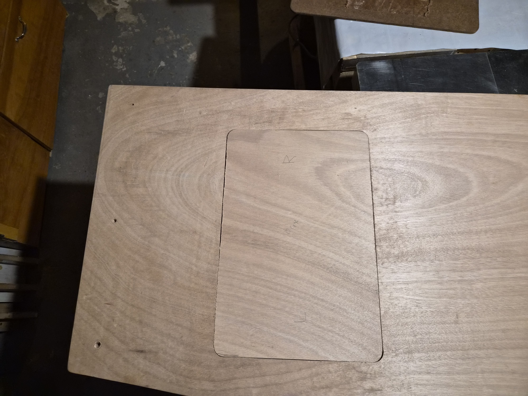
The blank fit nicely in the larger part of the opening. I now had to create a rabbit in it to match the wall cutout.


Turning back to the router lift, I installed the rabbit bit and after some test cuts on scrap wood to get the depth set properly, I cut the rabbit into the door.


I ended up with a nice flush fit.

Please Log in or Create an account to join the conversation.

1971 Glasspar Newport Cruiser - Rejuvenation 1 month 3 days ago #149570

  • Larsspar
  • Larsspar's Avatar Topic Author
  • Offline
  • Senior Boarder
  • Senior Boarder
  • Posts: 248
  • Karma: 5
  • Thank you received: 21
Carrying on with completion of the walls, I wanted to share the tuning process I used to get the walls to decently fit the hull.


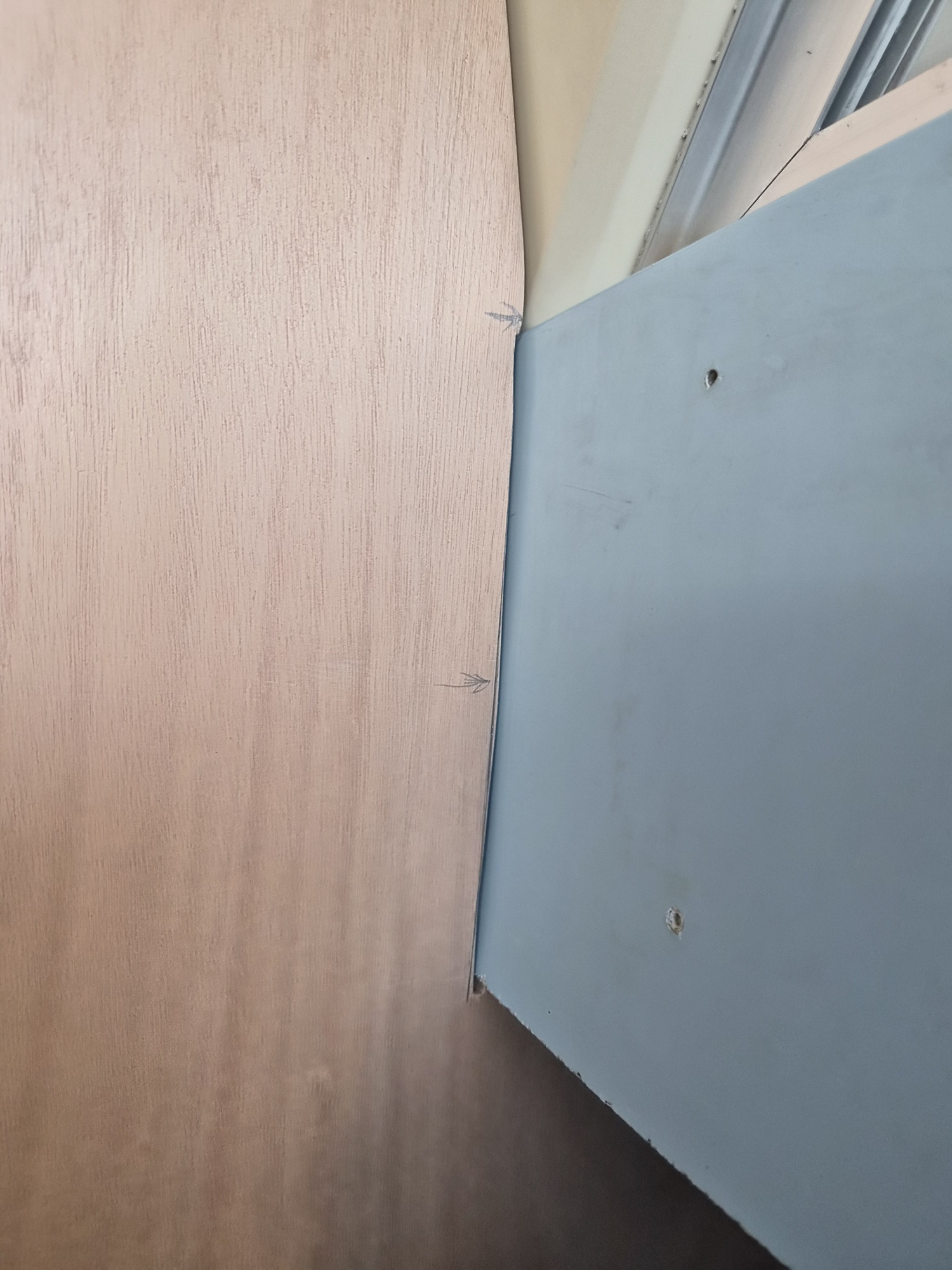
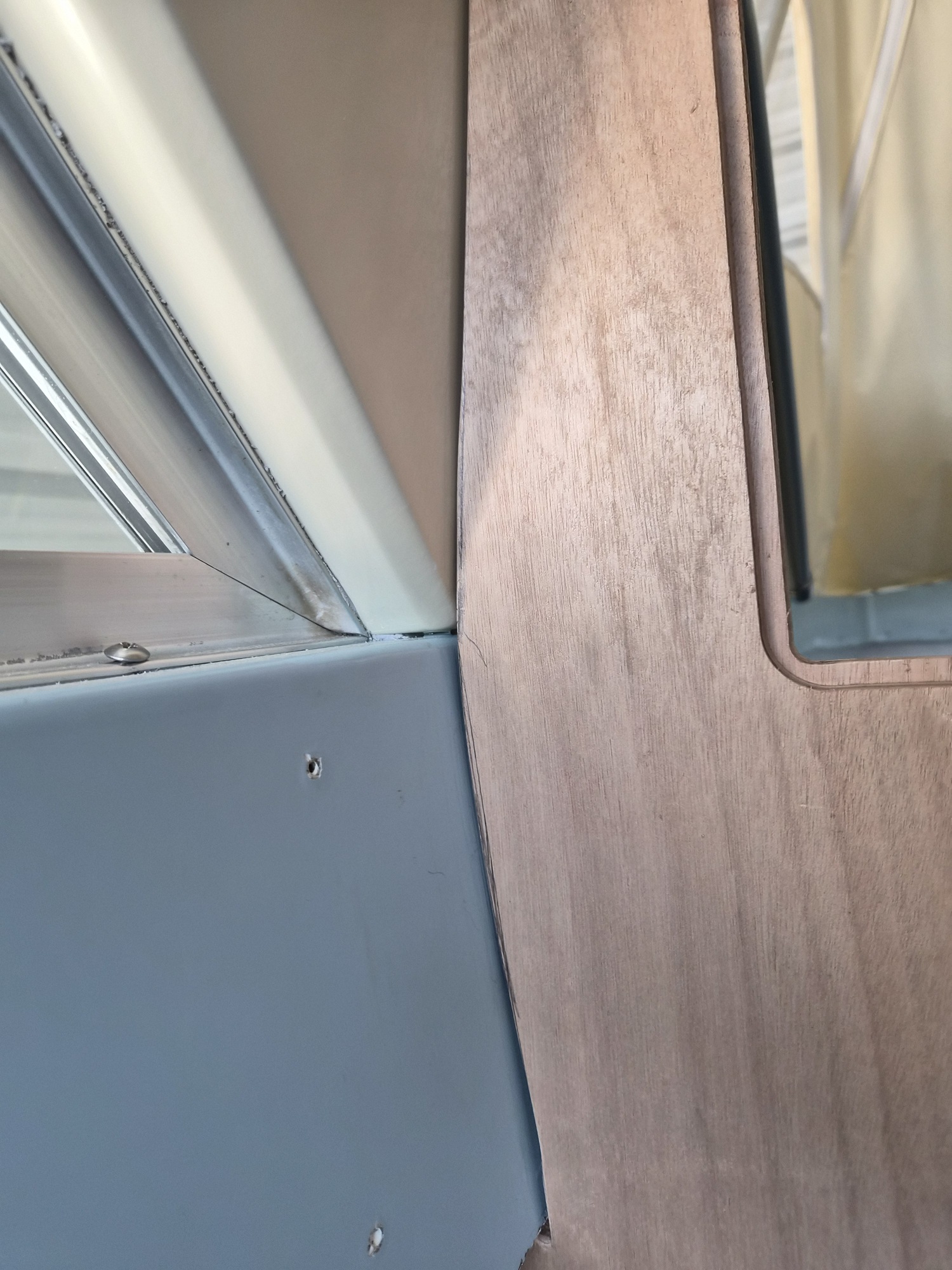
Much fiddling went on with pencils and a random orbital disk sander as the adjustments were minute and done a couple at a time.


I wanted even space lines along the ceiling.


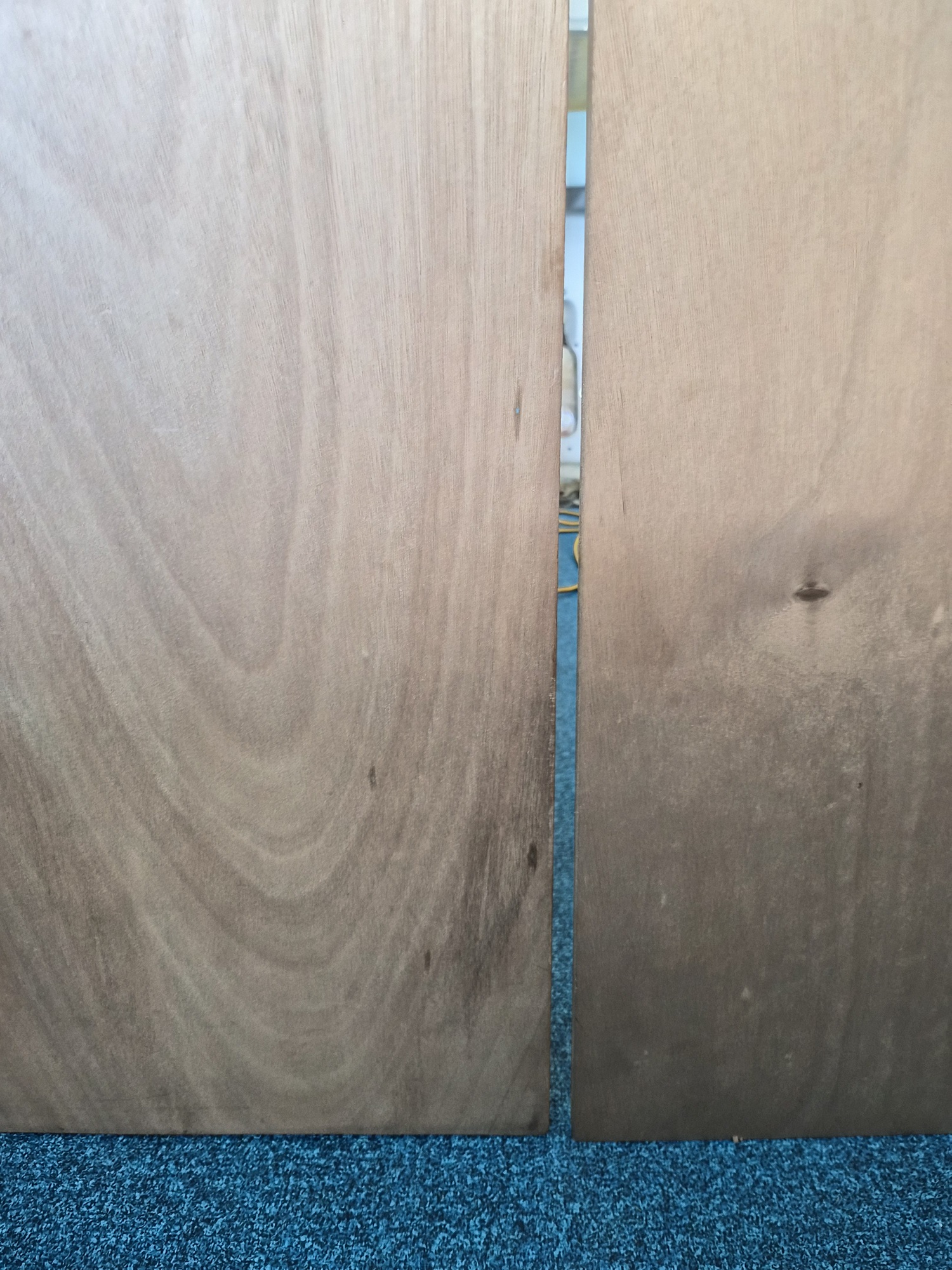
Gap between door and both walls was not square.


The floor was a pain in the neck as it’s rolling versus flat.


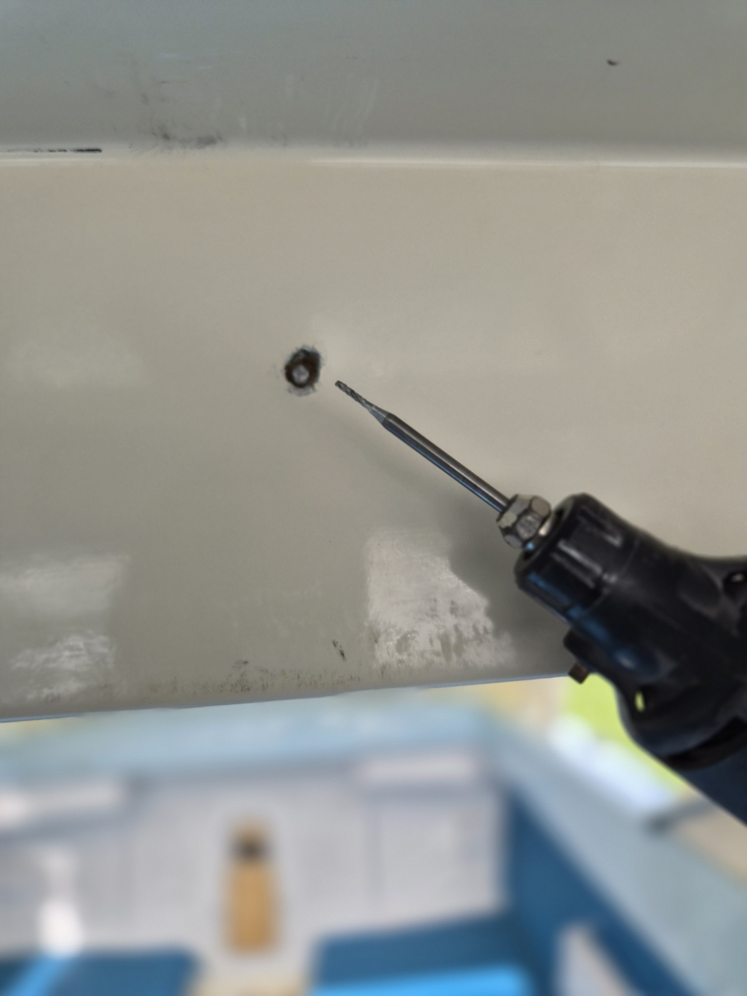
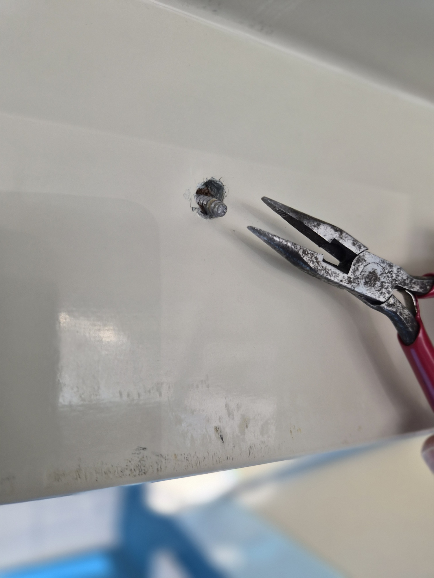
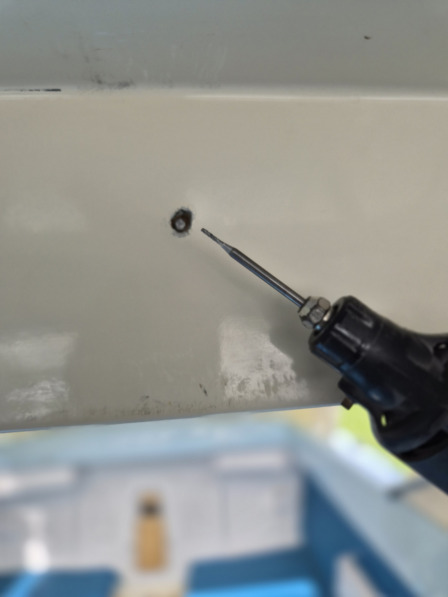
There were two screws that attach the walls to the cabin roof header that had sheared off. I used a Dremel tile grout bit, (smallest cutter I could find) to route around the broken screws.


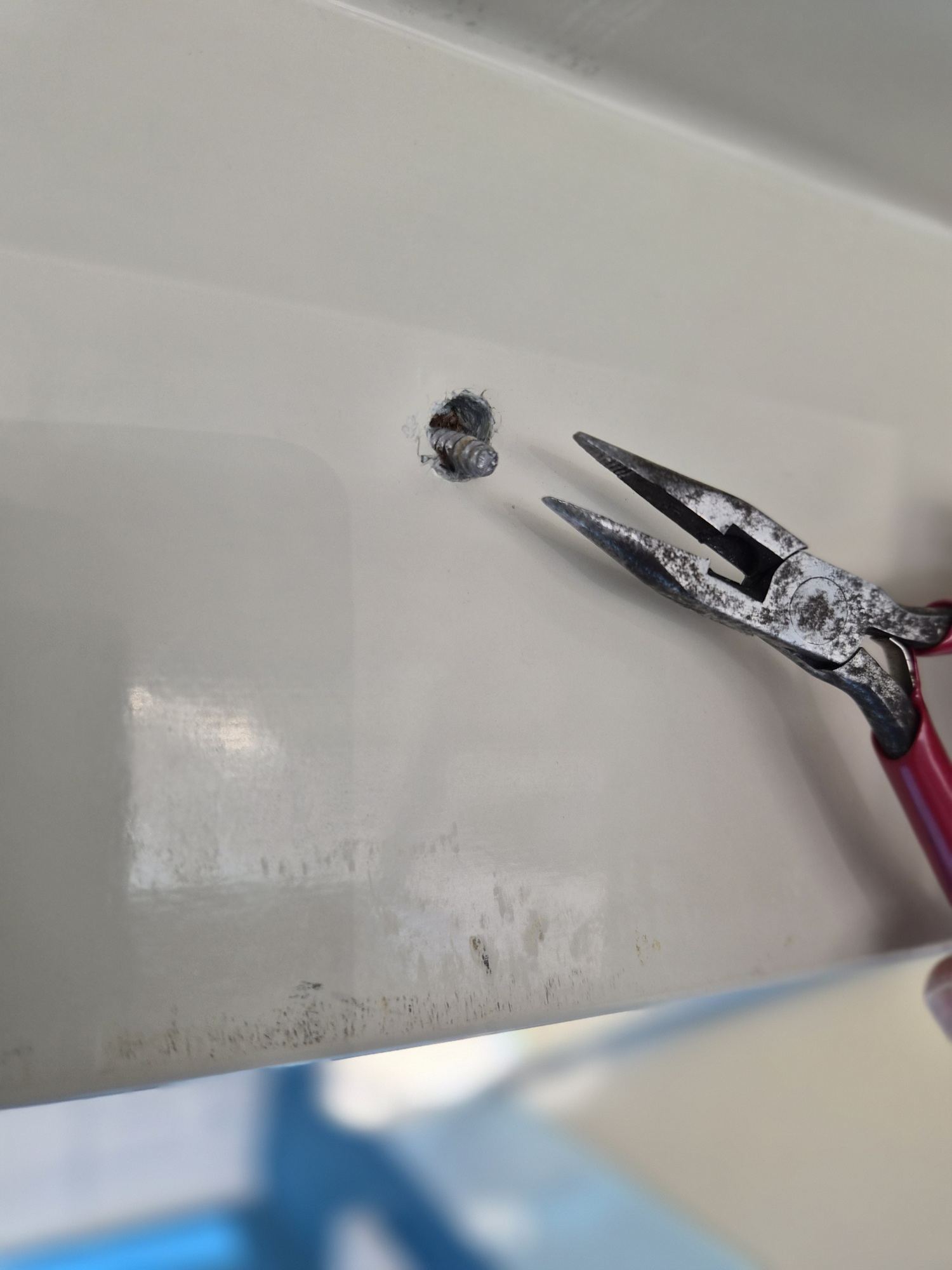
The opening created allowed me to use a small needle nose pliers on each screw and twist them out. Once the screws were removed, each of the holes was filled with West Systems Six10 epoxy injected through a glue syringe and covered over with clear box tape to keep the epoxy from flowing out of the holes. Once dry, new 1/8-inch holes were drilled.


Starboard wall installed. I present this picture because all the other cabin components and the helm installation all depend on the proper fit and alignment of this piece. It had to be square to the floor, ceiling, and roof header.


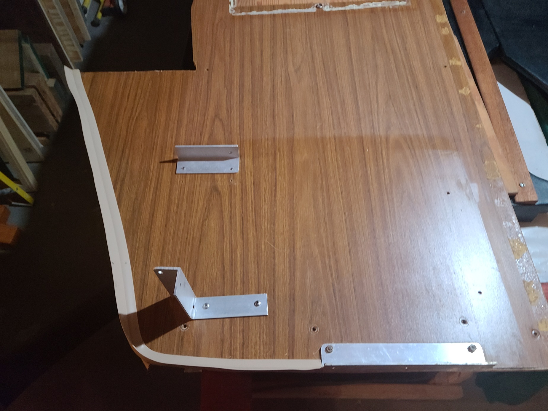
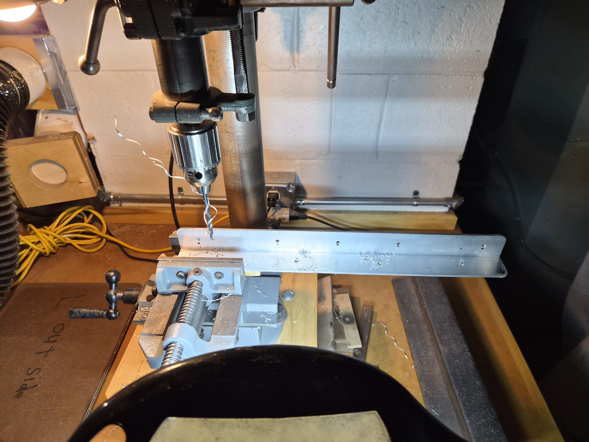
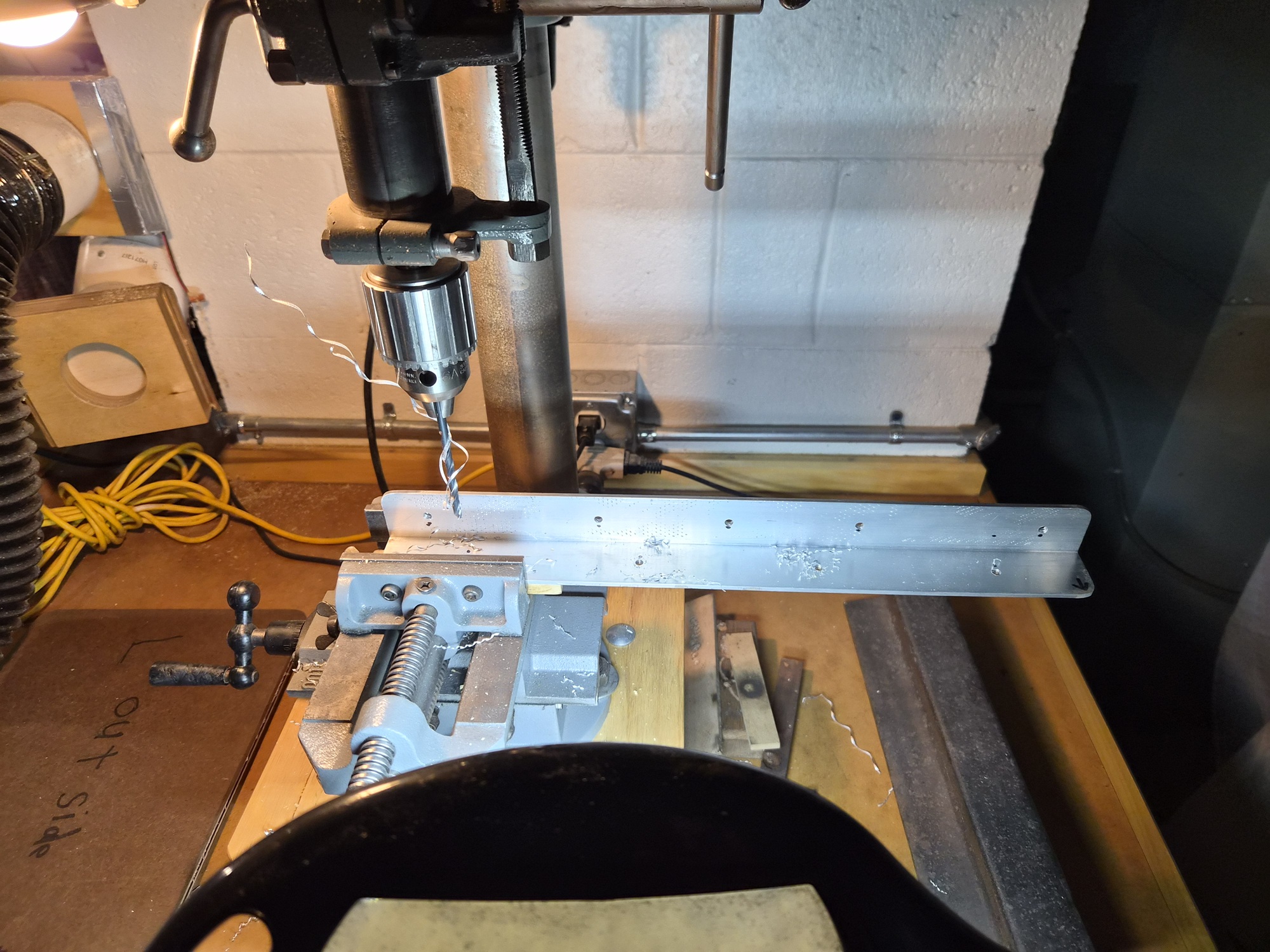
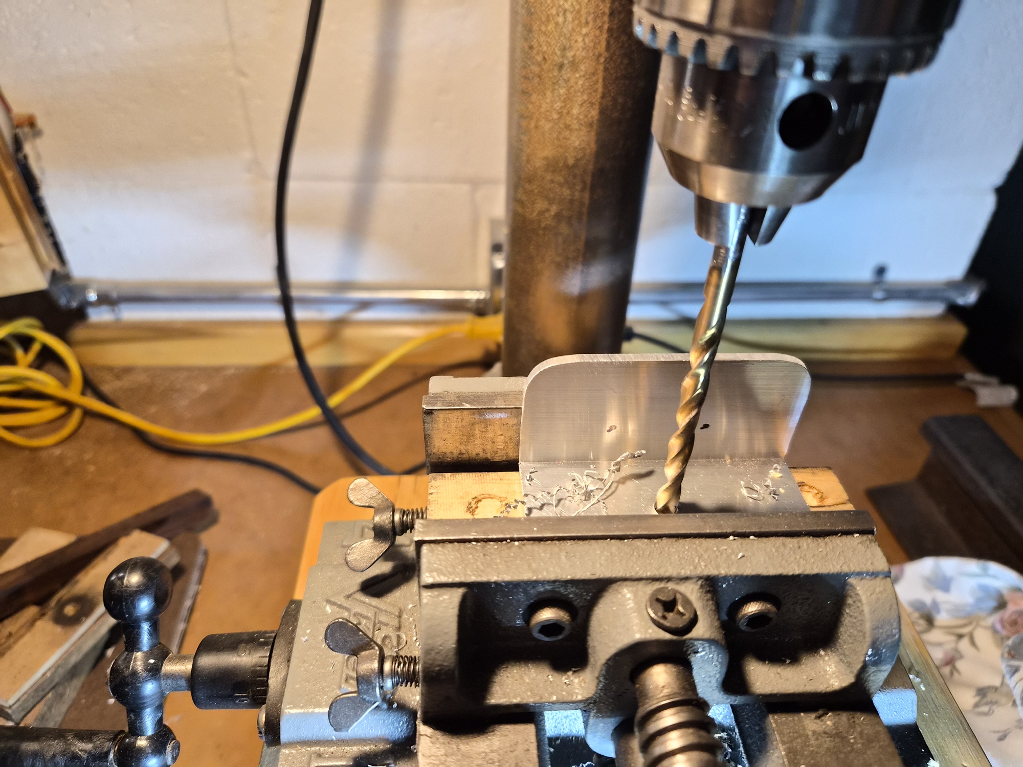
Last step to install the walls was to create a bracket for each of the port and starboard sides. The brackets are cut out of 1/8-inch thick 1-1/2-inch angle aluminum. I cut each piece to length on a chop saw. Rounded the edges on a stationary sanding disk and drilled 3/16-inch holes on the drill press.

Please Log in or Create an account to join the conversation.

1971 Glasspar Newport Cruiser - Rejuvenation 1 month 3 days ago #149571

  • Larsspar
  • Larsspar's Avatar Topic Author
  • Offline
  • Senior Boarder
  • Senior Boarder
  • Posts: 248
  • Karma: 5
  • Thank you received: 21
Once the cabin walls were finished and attached to the cabin roof header and boat floor, I focused on the door.


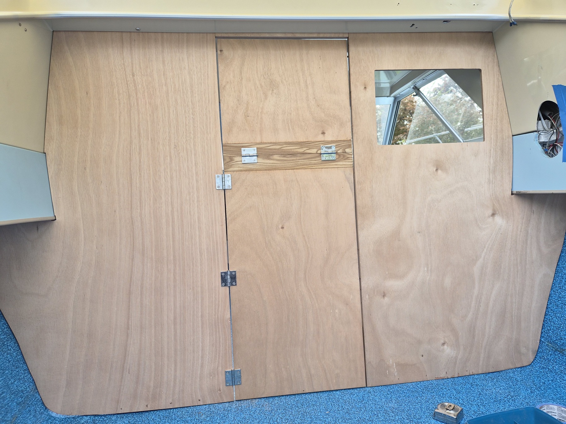
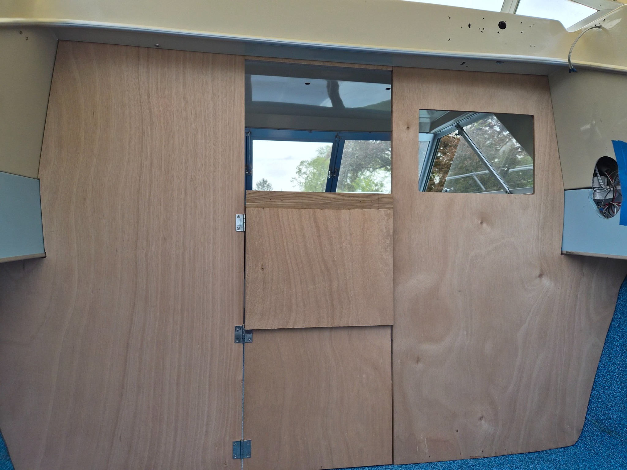
I've always admired the Glasspar Seafair Sedan cabin doors, so I set out to create a 70's Disco-fiber version. After some discussion with the Chief Investor (wife) we settled on dimensions for 2/3's lower door, 1/3 upper door. Started by fitting the lower door to the opening and tuning the shut lines using shims. Then used a 1/8-inch Vixbit to drill the hinge screw holes which really helps produce accurate hole placement.


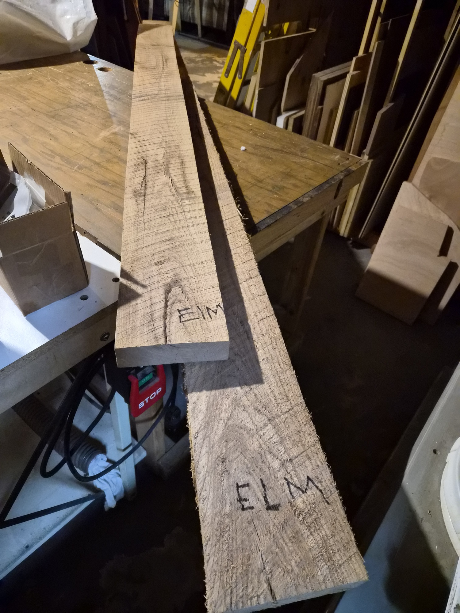
Went to my local hardwood lumber shop, Kettle Moraine, and found some locally sourced elm. I figured since the boat has simulated elm vinyl, why not try adding some real elm accents.


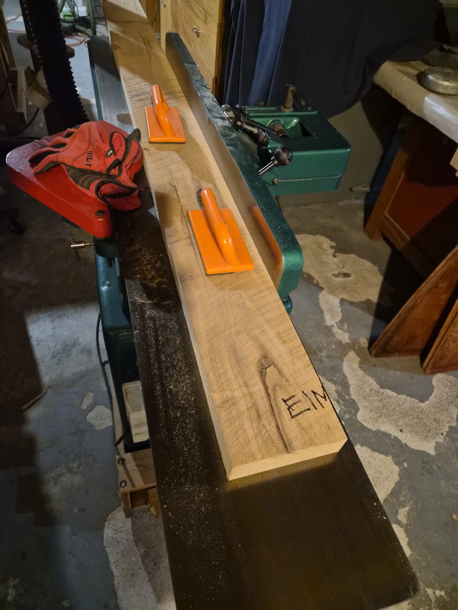
I milled it up on the jointer and planer. Two thicknesses were purchased, four-fourths and six-fourths for different purposes.


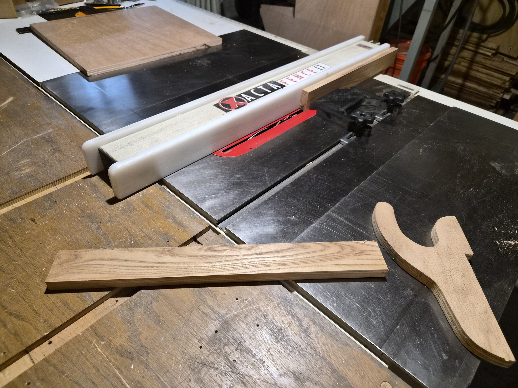
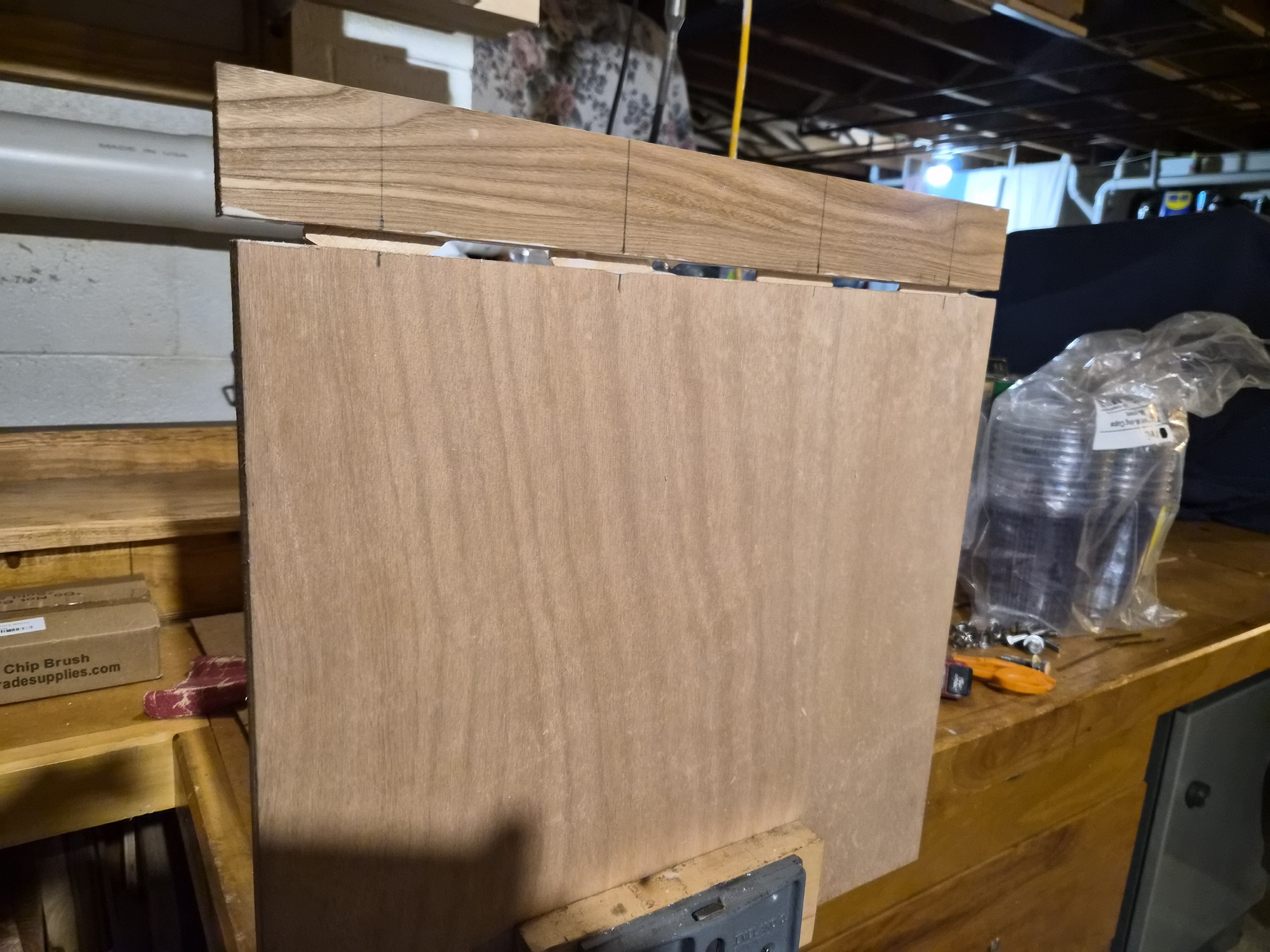
Milled the four-fourths board down to 3/4-inch thickness to use as part of the hinged portion of the door panel. Using the table saw, a 3/8-inch by 3/8-inch rabbit was ripped into each board, creating the interlocking joint.


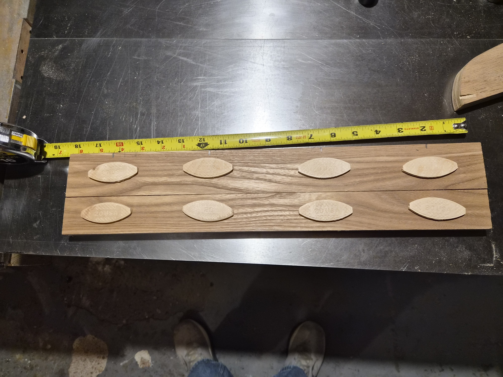
The boards laid together at the rabbit joint, #20 biscuits were laid out.


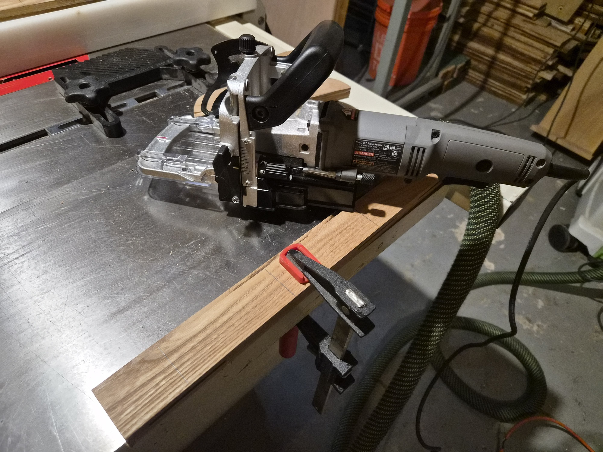
Used the biscuit jointer to create reliefs in the elm and marine plywood door pieces.


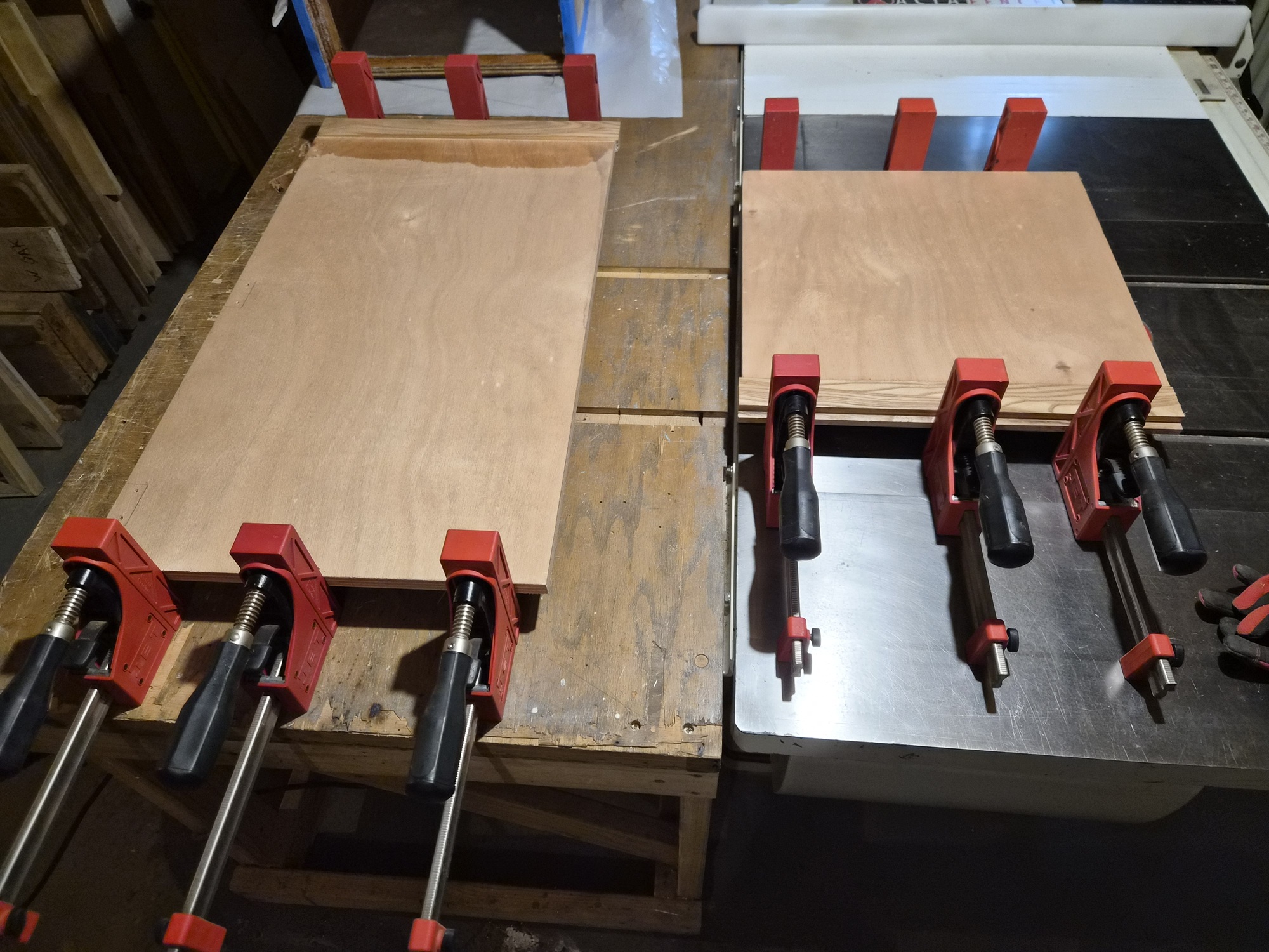
The always nerve-wracking glue-up. Used Titebond III wood glue.


Both door pieces in clamps for the night.


Assembled in place.


Folded down.

I've still have yet to identify locking latches for the upper and lower portions of the doors. I'm seeking something sized for 3/4-inch-thick wood that is appropriately scaled for this modest door. Must work inside and out. If you have any suggestions, please share......

Please Log in or Create an account to join the conversation.

1971 Glasspar Newport Cruiser - Rejuvenation 1 month 2 days ago #149572

  • Larsspar
  • Larsspar's Avatar Topic Author
  • Offline
  • Senior Boarder
  • Senior Boarder
  • Posts: 248
  • Karma: 5
  • Thank you received: 21
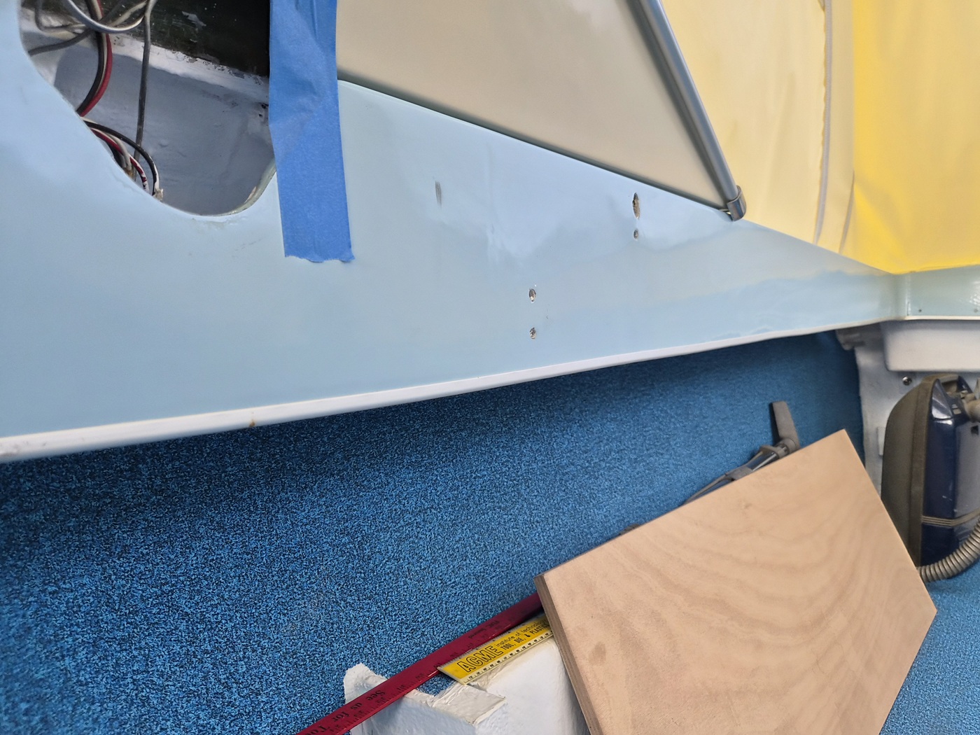
I test fit my nicely restored helm to the new cabin wall and boat floor and was disappointed to figure out it was now a little too tall by 3/8-inch. Also, I determined the starboard surface of the cabin roof which meets the side of the helm (steering wheel/gauge level) was bulging outward, leading to a very poor fit.


I was lucky the starboard surface of the cabin roof was not backed by wood. I was able to spend 15 minutes with a heat gun to heat the area up, making it soft and shapeable, and a 4-inch by 12-inch plywood blank used to reshape the surface flat and hold it into place while it cooled. This gave me a uniform fit.


In this picture, you can see how tight the helm is to the cabin roof.


I carefully trimmed 3/8-inch off the bottom of the helm which provided a more comfortable uniform fit. (see how it lines up nicely with the door opening) This allowed me to drill and screw mounting points through the starboard cabin wall, into the helm.

Still, the gauges for the top cluster won't fit properly. I'll have to remove the simulated burl elm vinyl from the cluster blank and shave the blank down ½-inch. A couple steps forward and a half step back.

This is a good segue into the bunk build out.


As you can see, I attempted to loosely reinstall the original bunk frames and cushion bases. Not surprisingly, nothing was square, primarily due to parts not being sized to fit together well.


This starboard bunk frame illustrates the challenges. A middle divider between the hull and this frame was too long, forcing the frame into an ellipse. You can also see along the top edge, new lumber has been added. I assume this was done to elevate the bunks as the rails approached the cabin walls. I gather this need was based on how the stern sits in the water.


I didn't like how the cushion bases were made to lay on top of the frames. I wanted to make them captive inside the frames so they will be secure while underway.


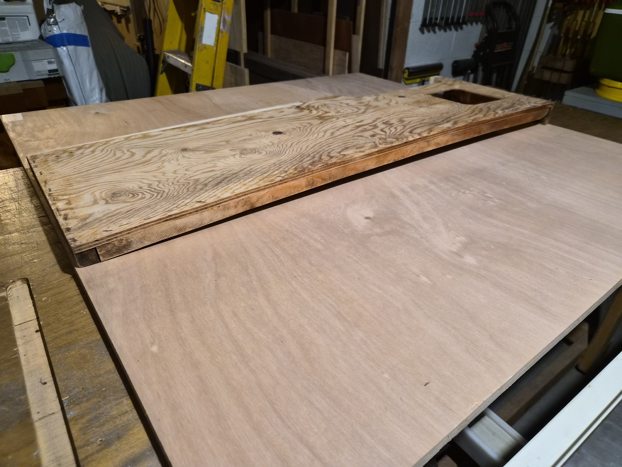
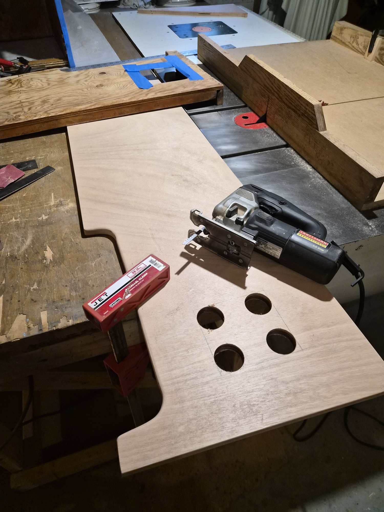
I started the process by recreating the bunk rails using the revised profile. Here, I've drilled four holes to create the opening for the Porta Potti flush pedal.


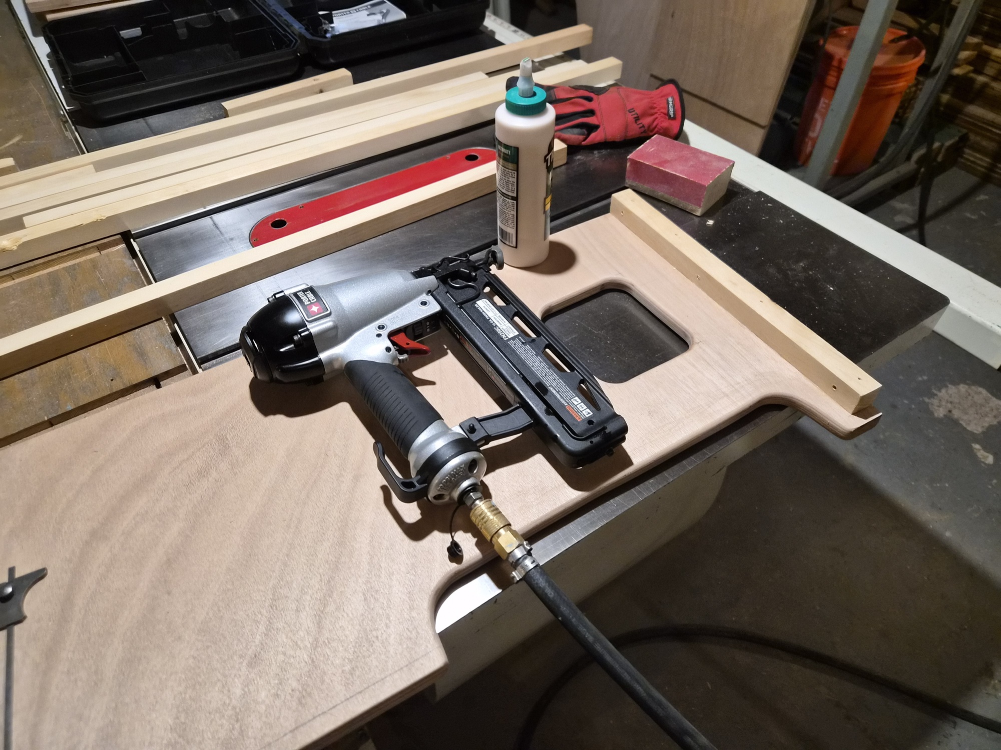
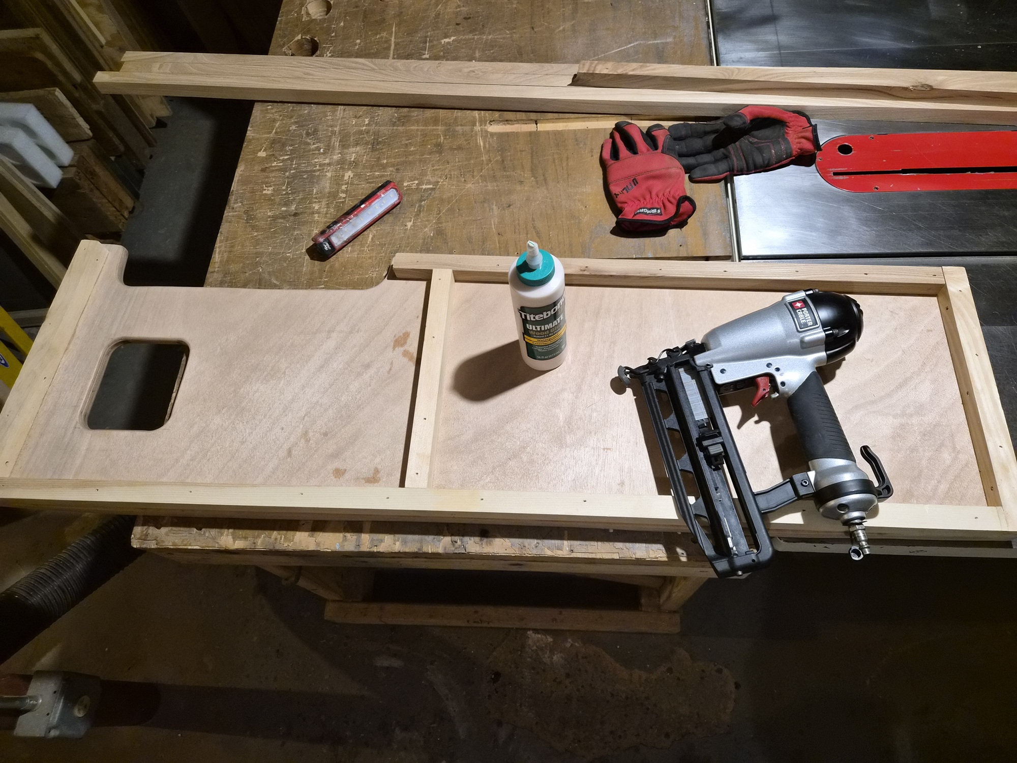
Next, carefully/thoughtfully applied blocking to the plywood using Titebond III wood glue and 16-gauge Brads. The blocking serves a couple purposes. Mounting point to cabin walls, boat floor and other bunk components, and railing for cushion bases to rest on. I left a 1/2-inch relief along the top to keep the cushions bases captive.


I used elm for the top/visible cushion base blocking and white pine for the rest. The trigger on my Brad Nailer failed at this point, leaving me to research a fix. Turns out this is apparently a common Porter Cable failure with this tool. I had to order a new trigger assembly, which took a couple days to arrive.


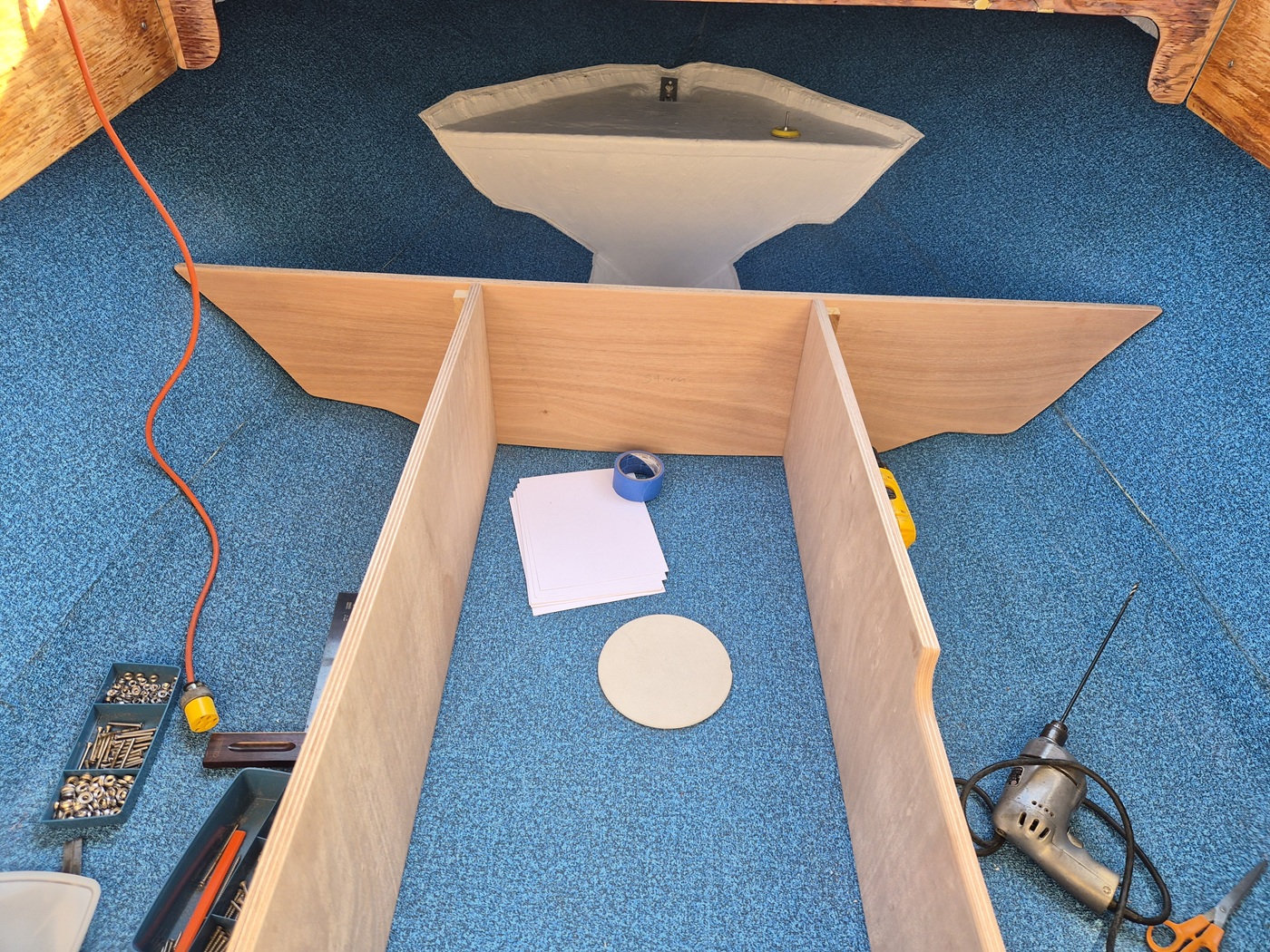
Bunk rails installed square to the cabin walls (secured by three screws each), and the boat floor. (secured by one screw each) I temporarily attached the rails to the original cross-member.


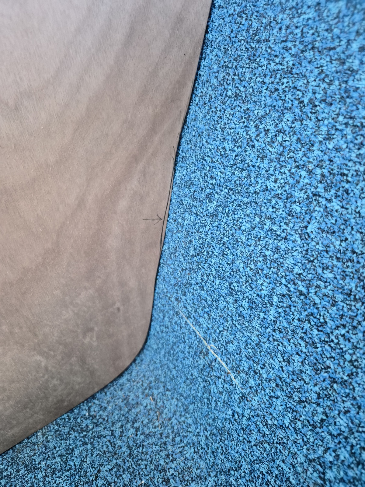
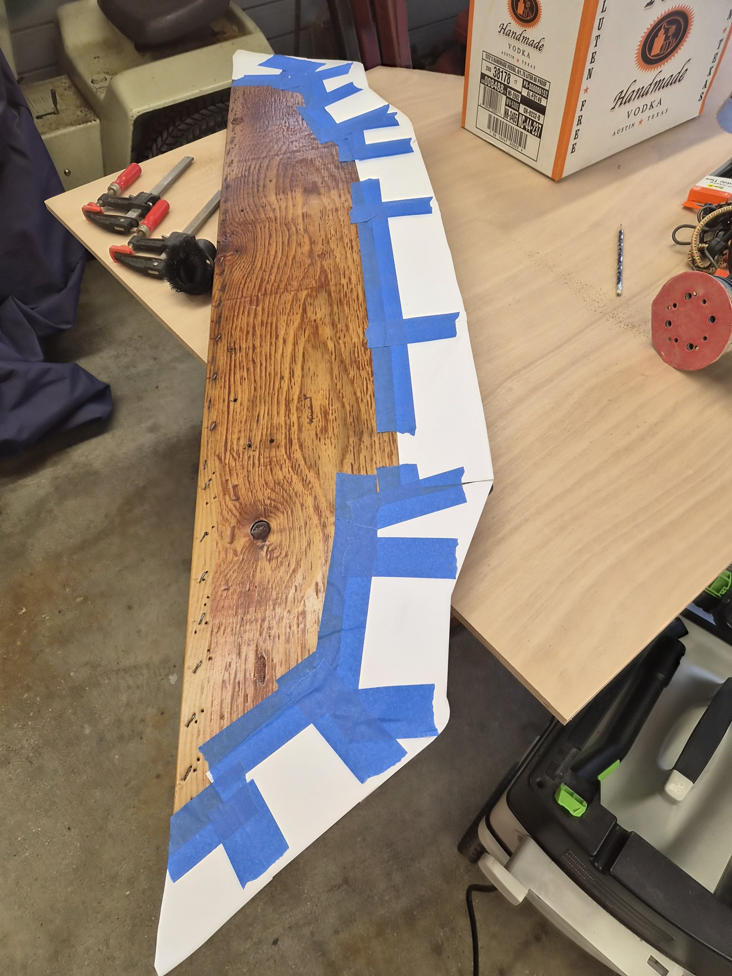
I used card stock/painters tape to template a tighter fit to the hull.


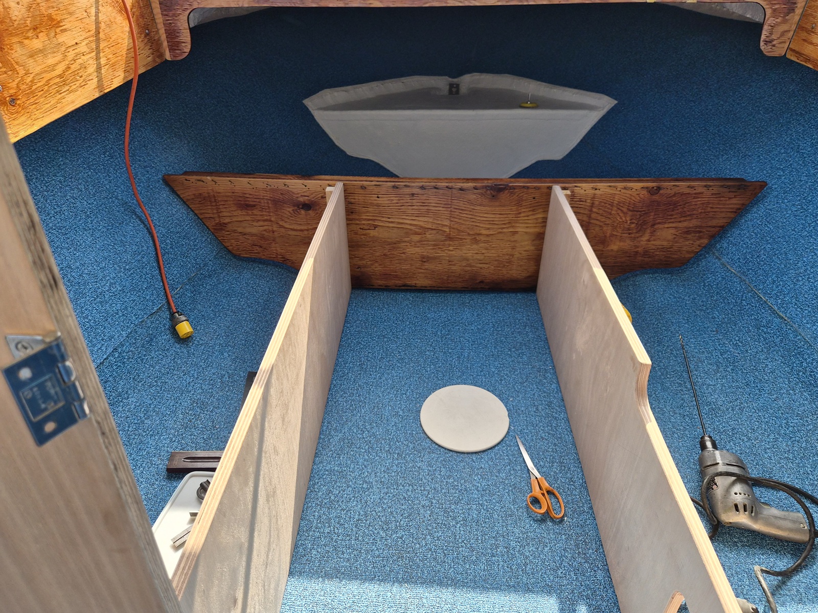
I traced the new template onto 3/4-inch marine plywood and cut the new cross-member out using a scroll saw. After a little sanding, I had a nice fit. The cross-member was attached to the boat floor using two 3-inch angle-aluminum brackets and three screws through each bunk rail end block. Very sturdy.

I went on to create two dividing cross-members and an end cross-member which attaches to the floatation foam compartment in the bow. Pictures in the next post.


One of the angle aluminum brackets created to tie cross-members to the boat floor. Made four of these 3-inch versions.

Please Log in or Create an account to join the conversation.

1971 Glasspar Newport Cruiser - Rejuvenation 1 month 2 days ago #149573

  • Larsspar
  • Larsspar's Avatar Topic Author
  • Offline
  • Senior Boarder
  • Senior Boarder
  • Posts: 248
  • Karma: 5
  • Thank you received: 21
The final component needed to complete the cabin mockup required some re-engineering of the boat industry. I wanted to add a stringer to the port and starboard sides which ties the cabin walls, the cross-members and the bow flotation foam compartment together.


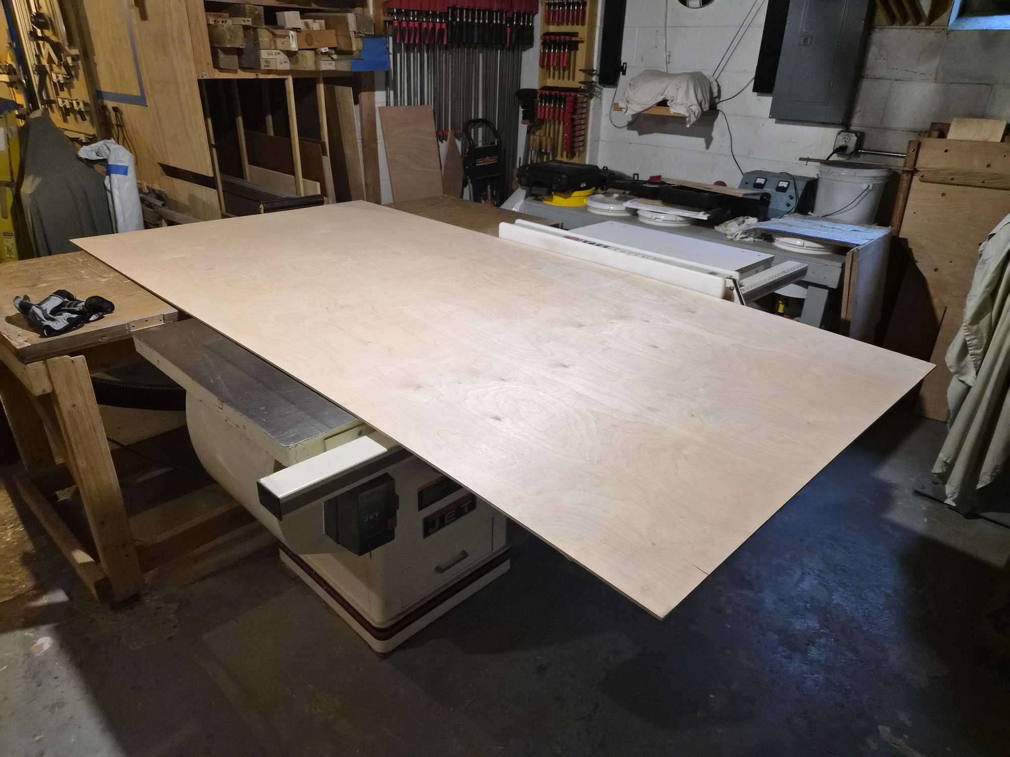
I was running low on hardboard, so decided to sacrifice a 1/4-inch piece of plywood. The cabinet saw in my small shop is positioned so I can barely rip four-foot by eight-foot sheets of plywood. You can see the relief I cut in the wood storage rack at the same height as the outfeed table.


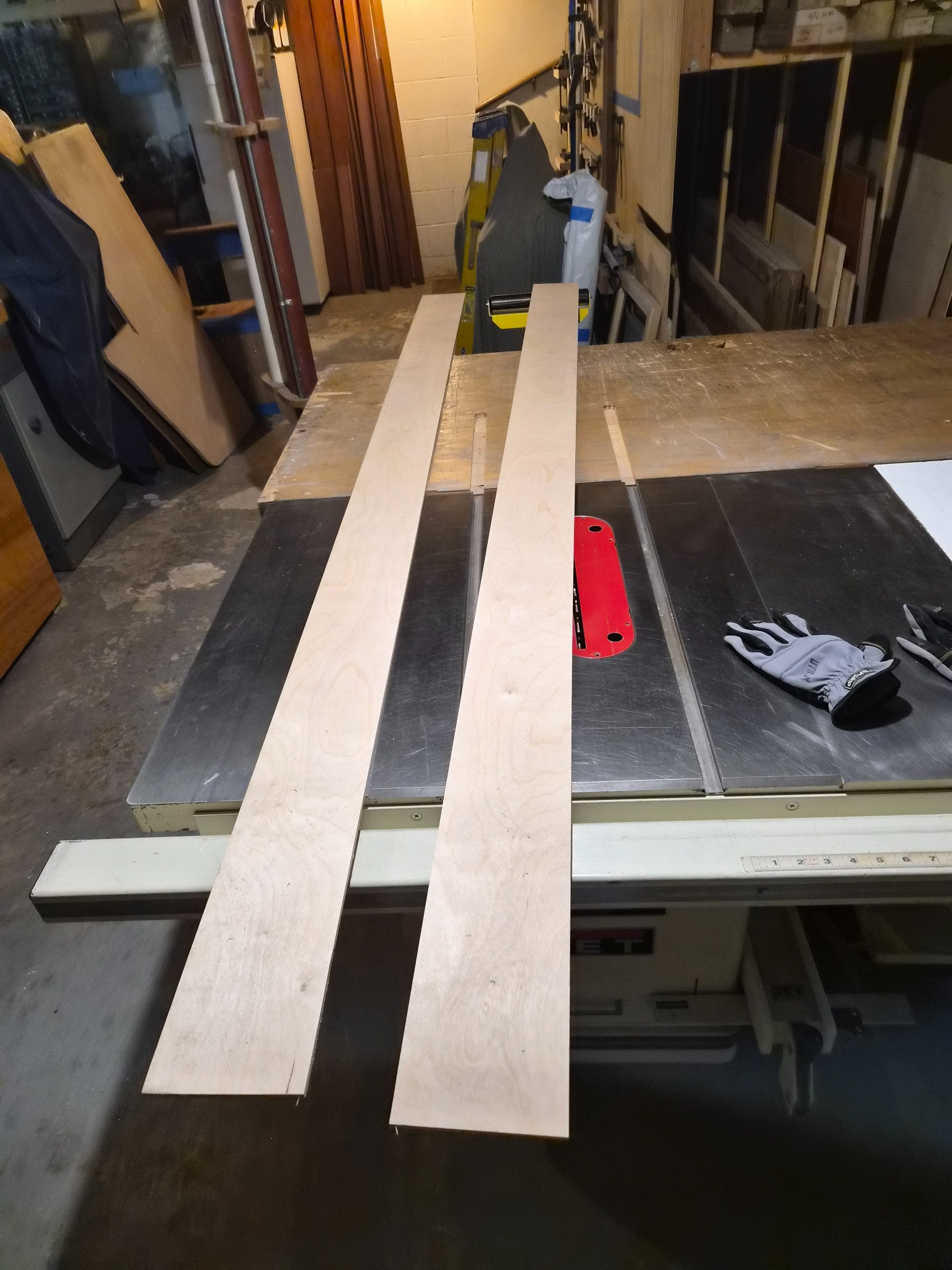
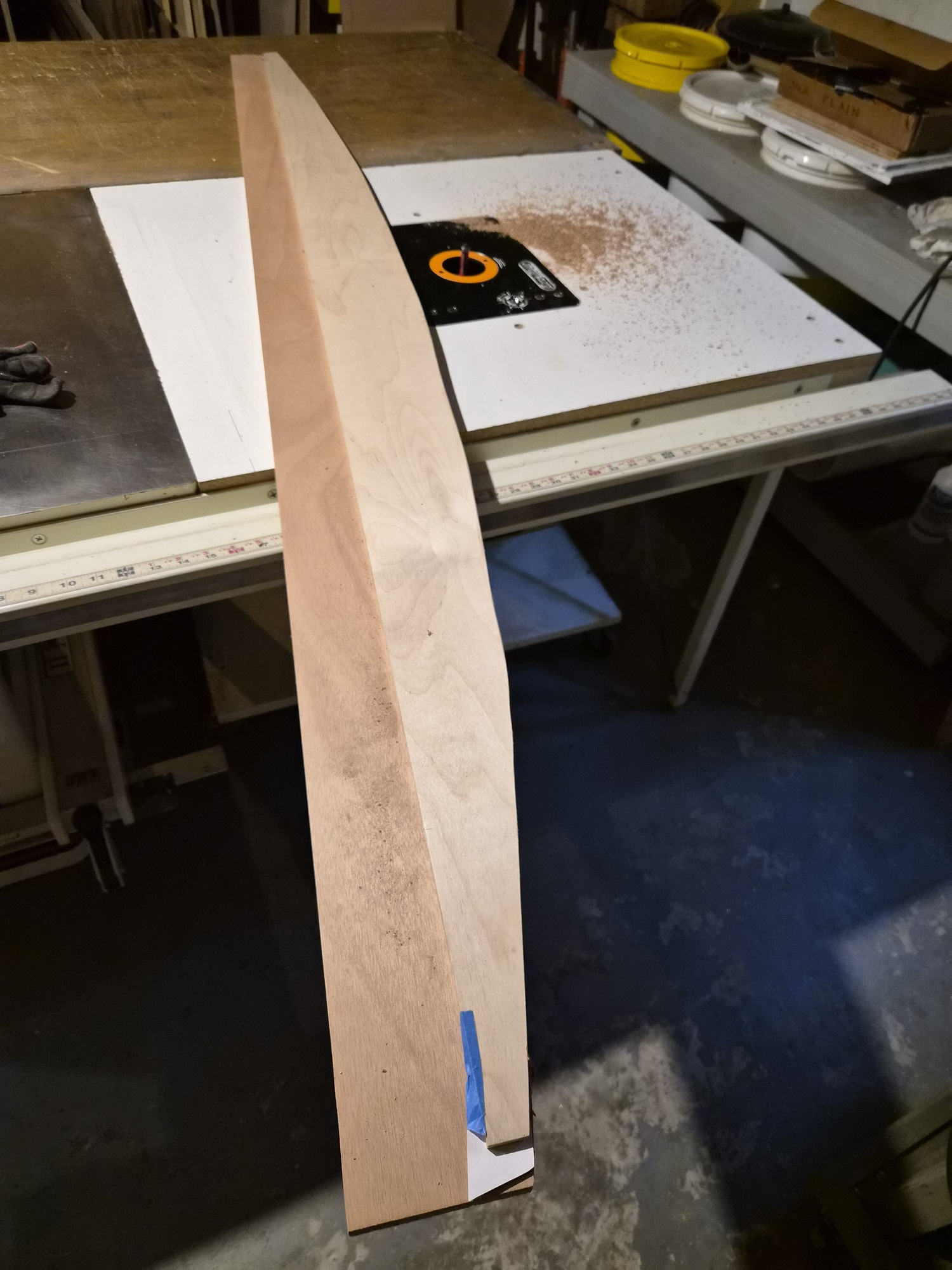
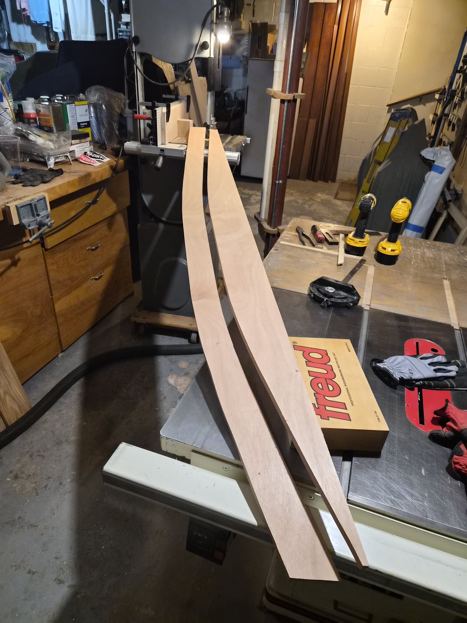
I ripped two five-inch wide blanks which were then chopped down to eighty inches long.


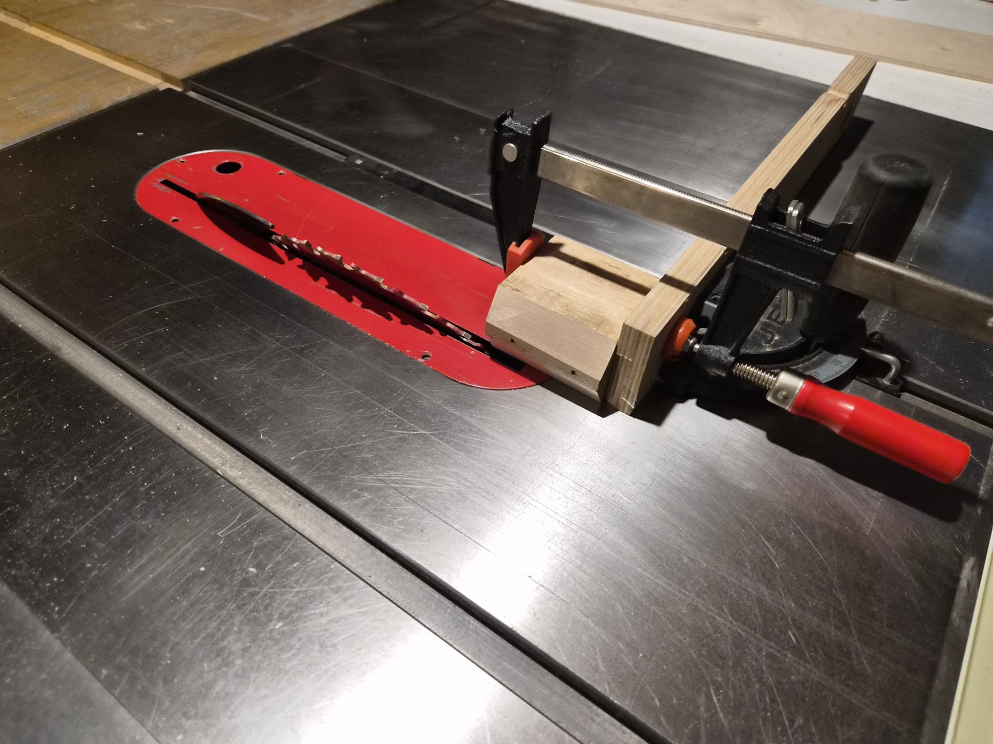
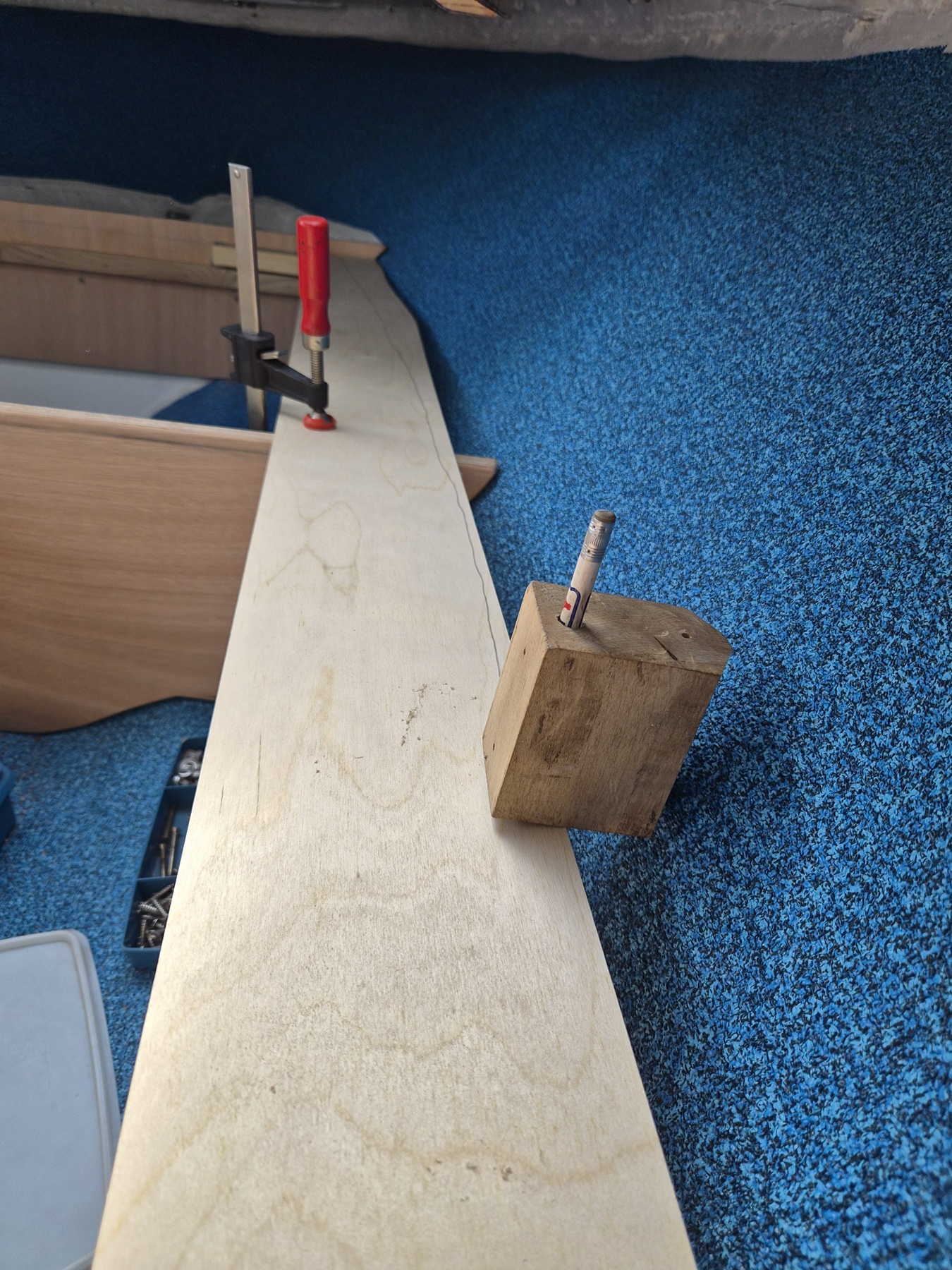
Using an old block of hard maple, a 30-degree chamfer was placed on two sides leaving a 1/4-inch nose in the middle. The block was then drilled vertically at the back edge with a 1/4-inch drill bit.


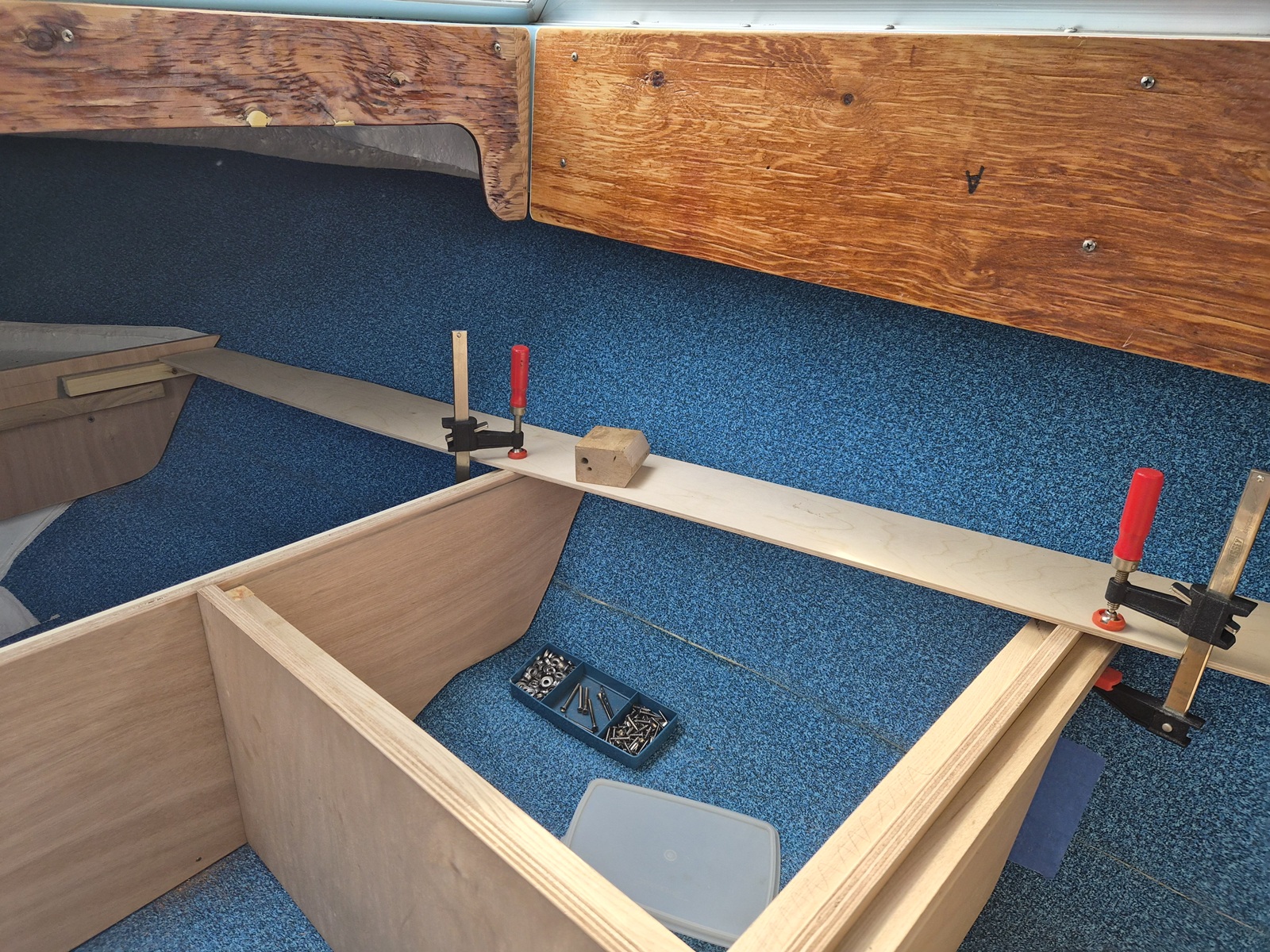
The stringer blanks were clamped in place.


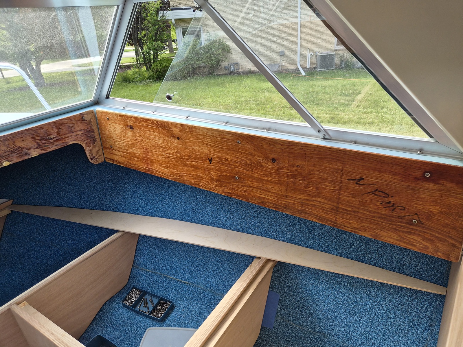
A pencil was inserted into the guide block, and the guide block was placed flat on the stringer template and then pressed into the hull side. As the block slid along, the pencil documented the hull profile on the stringer template.


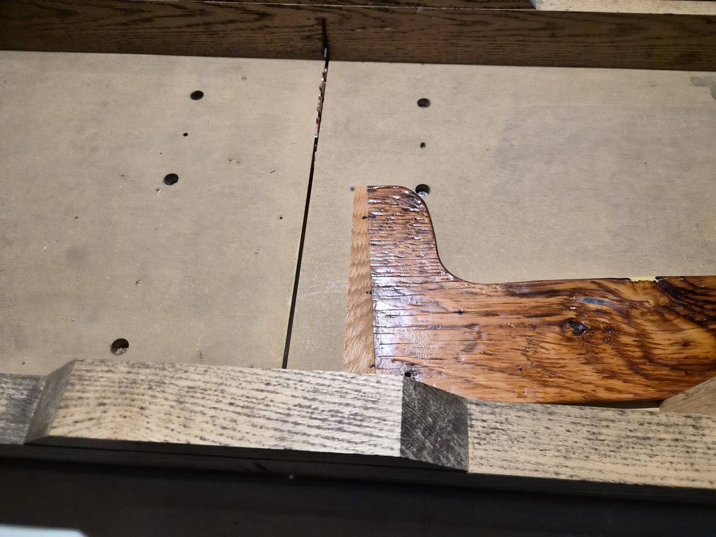
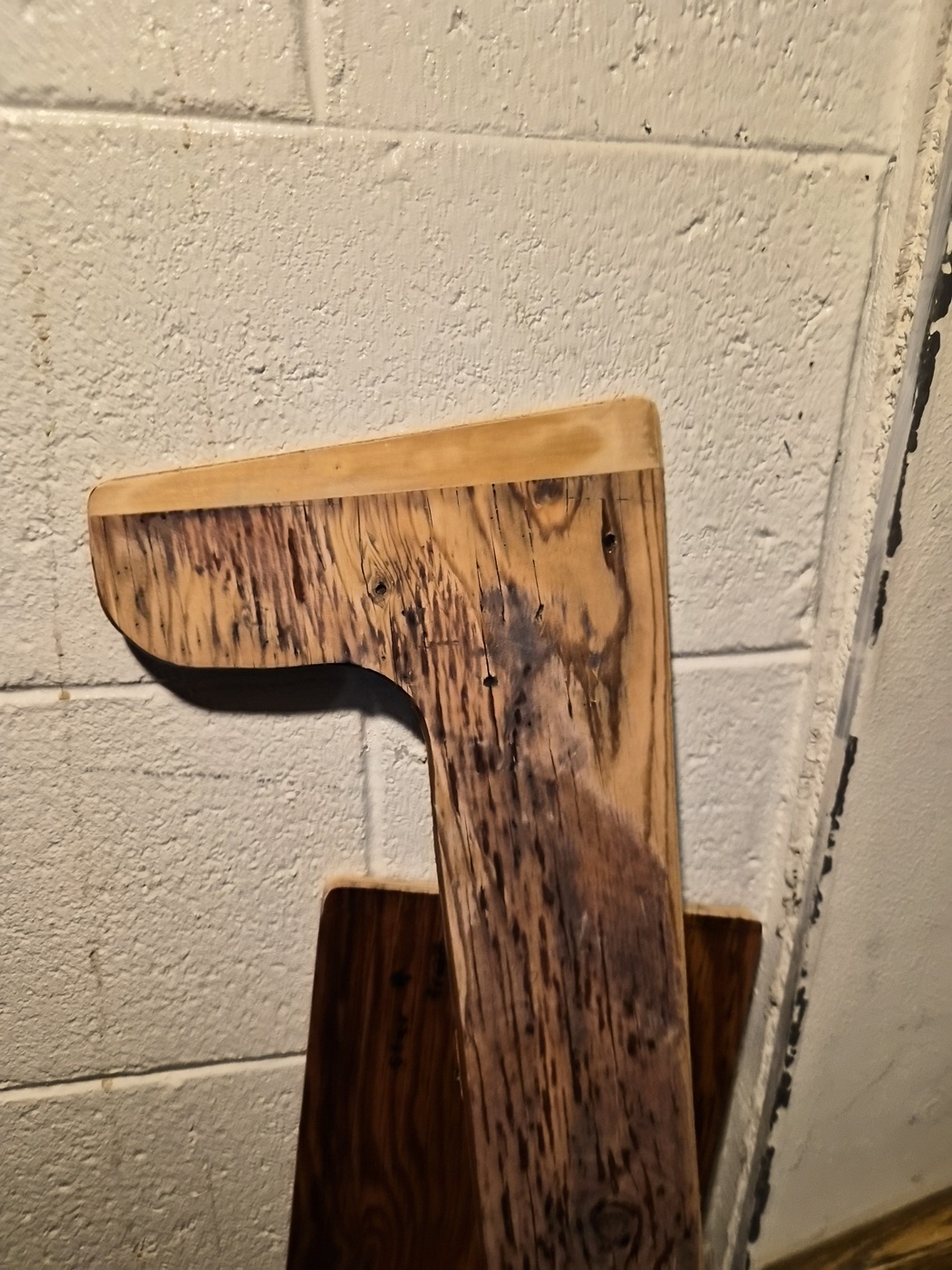
The stringer template was then trimmed to the pencil line using a scroll saw and faired using a sanding block.


Once I was happy with the template fit, it was taken into the workshop and attached to a 3/4-inch marine plywood blank. A flush cut router bit was used to match the plywood blank to the outer edge of the template. The template was then removed and discarded.


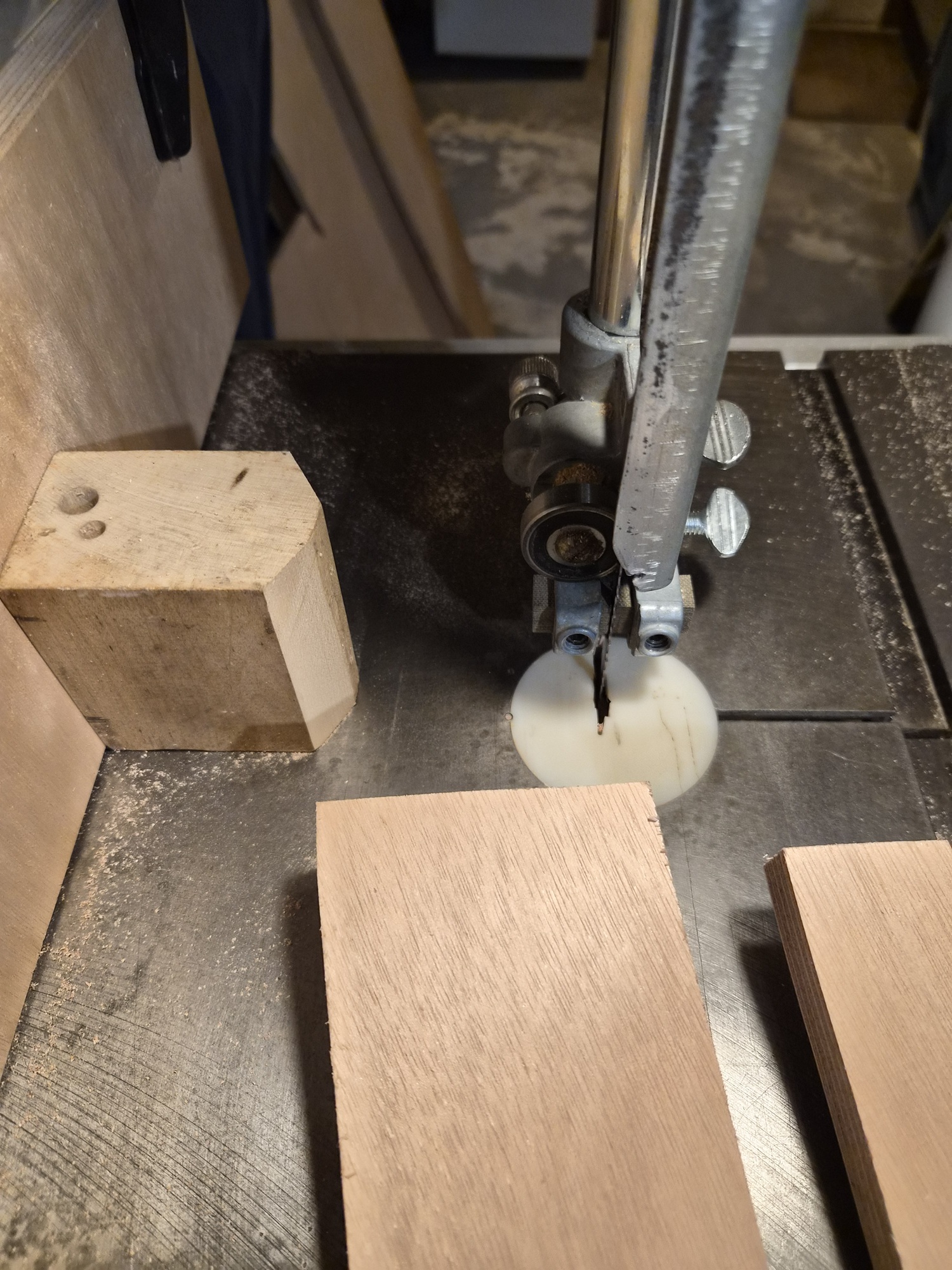
Rolled the old band saw into the shop and changed from a 1/2-inch to a 1/4-inch blade. The guide block used to trace the hull profile onto the template was now clamped to the band saw fence with the nose facing the blade, set three inches from the blade.


The routed edge of the plywood was kept pressed against the guide block while the board was passed through the saw. I ended up with stringers that have a freshly cut edge that mirror the routed edge.


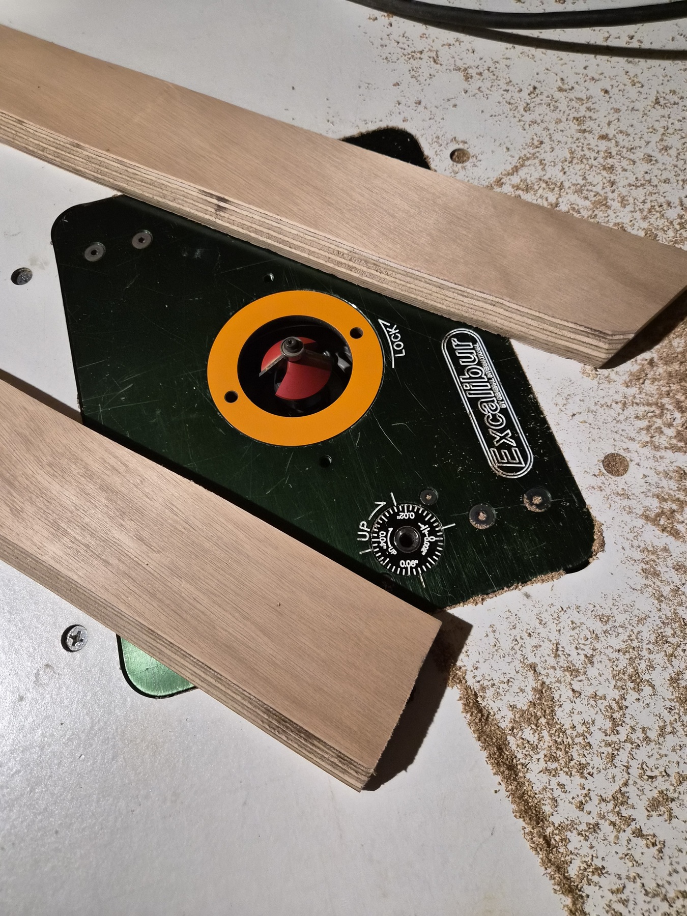
The newly cut edges were sanded smooth and then sent back to the router table where a 45-degree bevel cut router bit was installed. The height was set so only the bottom half inch would be beveled. This treatment was applied to the hull side of each stringer only.


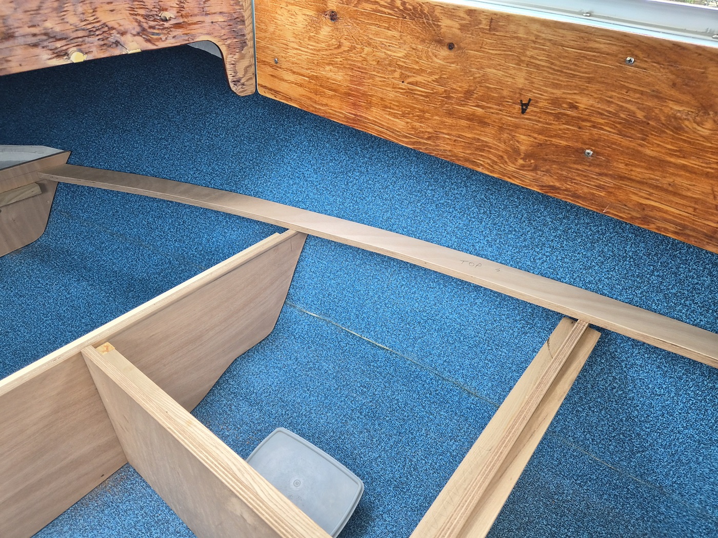
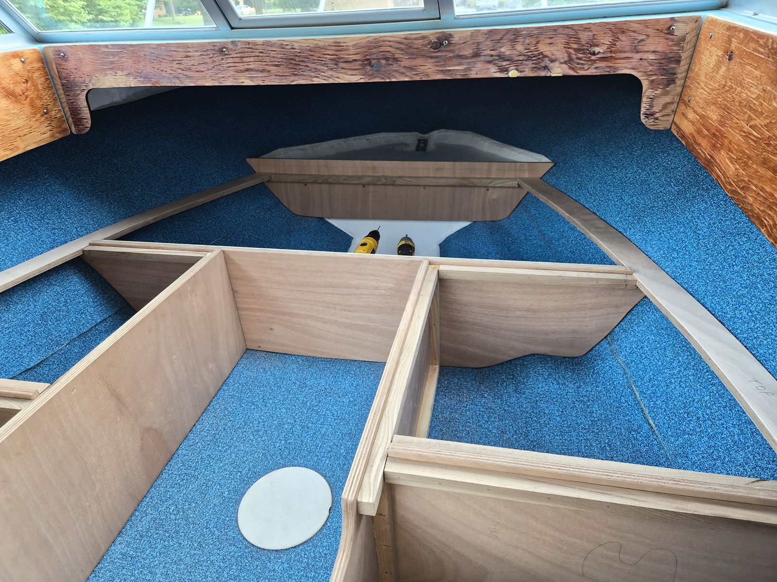
The newly completed starboard stringer was laid in place. I now needed to determine how to notch the cross-members so the stringers lay at the same height as the runners which will support the cushion bases.


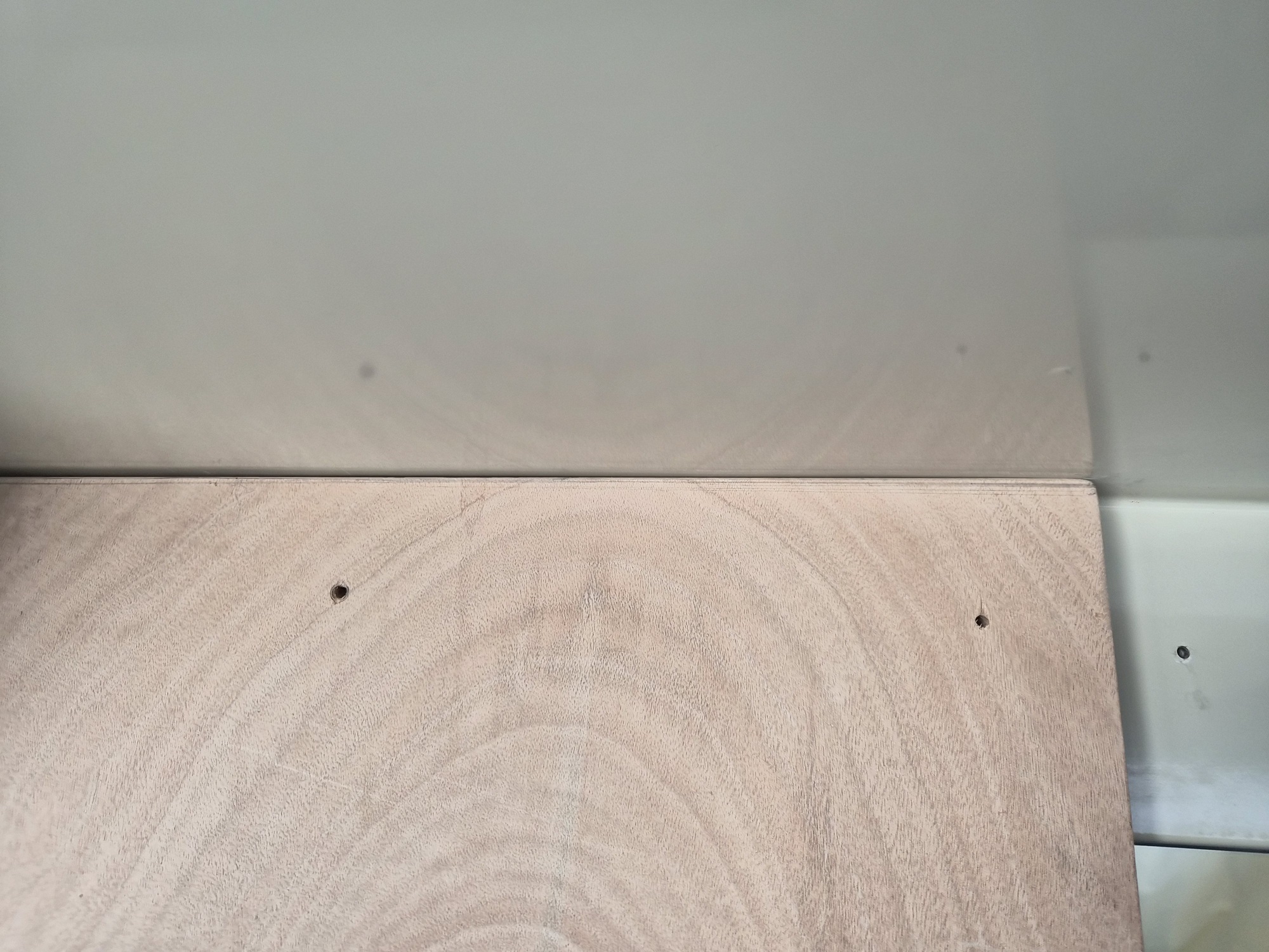
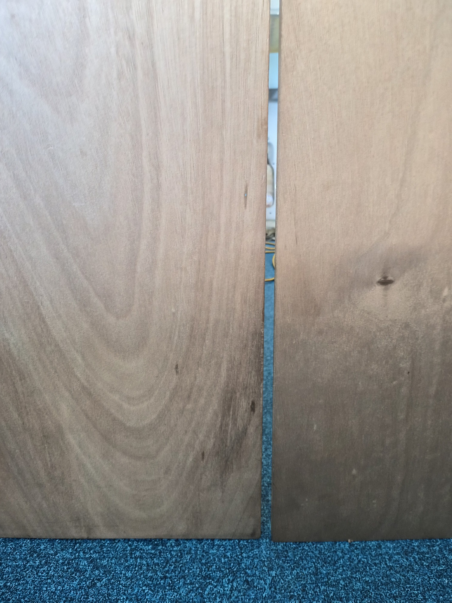
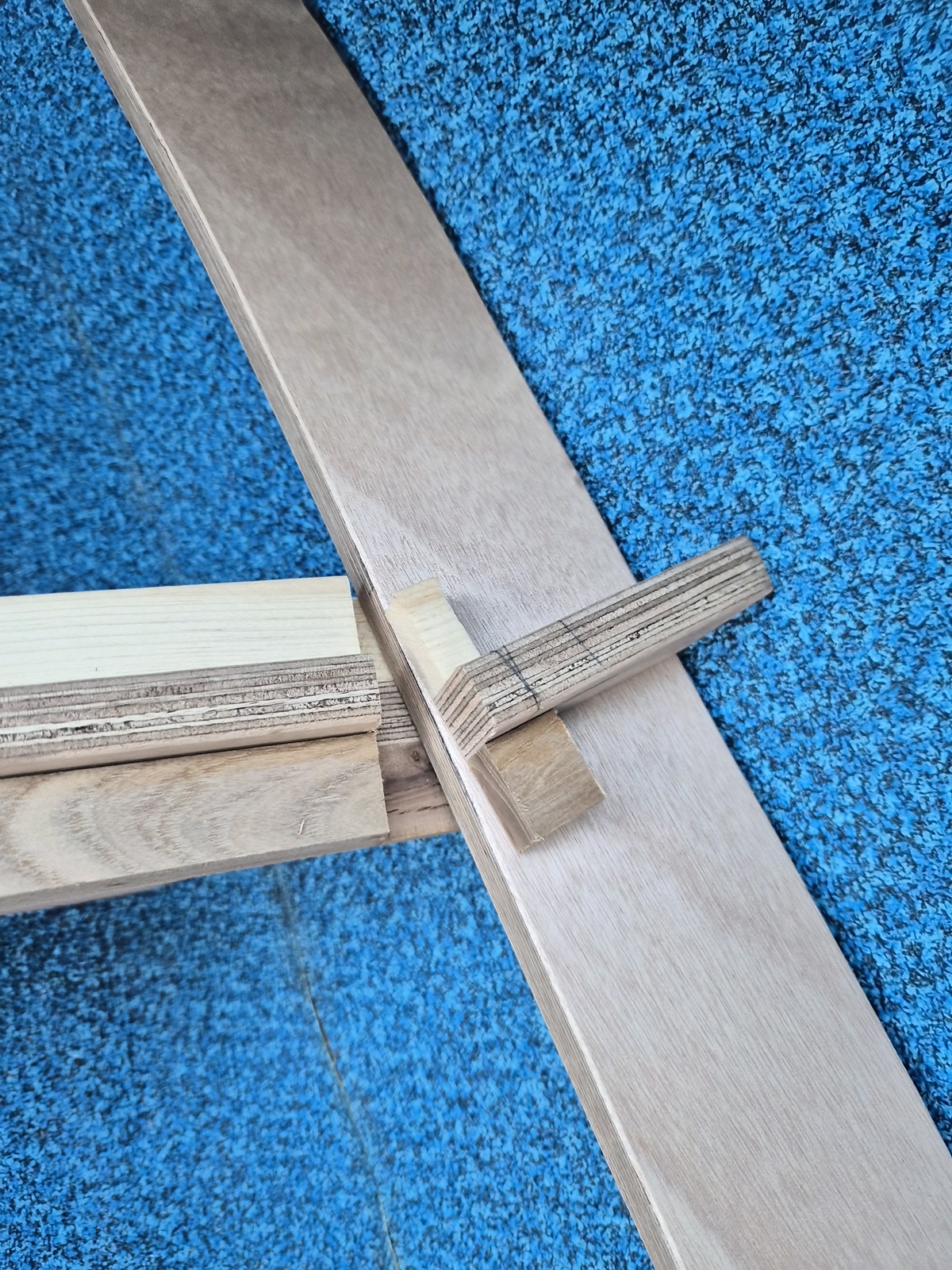
Some days I'm happy with the work I complete. Occasionally I shouldn't be allowed anywhere near this project. This was one of those days. I had in my head I needed to create three-inch notches in each cross-member end. (four total) Well, the stringers are curved and therefore don't cross the cross-members squarely. I ended up with this minor disaster. :angry: I defiled some pretty good work to this point. I needed to walk away for a little while.
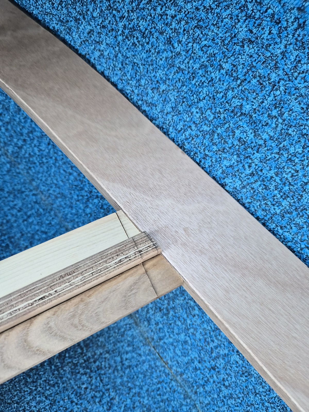
Through dumb luck I saved the cut-offs for each joint.


I marked each cut-off to match the gap I needed to fill. I was able to put the cut-offs into a vise and use a dovetail saw to precisely cut them. The results ended up creating a 'key' which holds the stringer in place. I now must decide whether I want to screw or glue the 'keys' in place.

I guess it doesn't look too bad...........


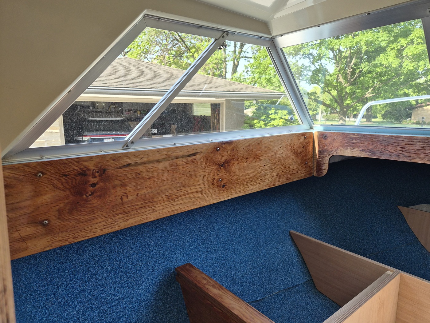
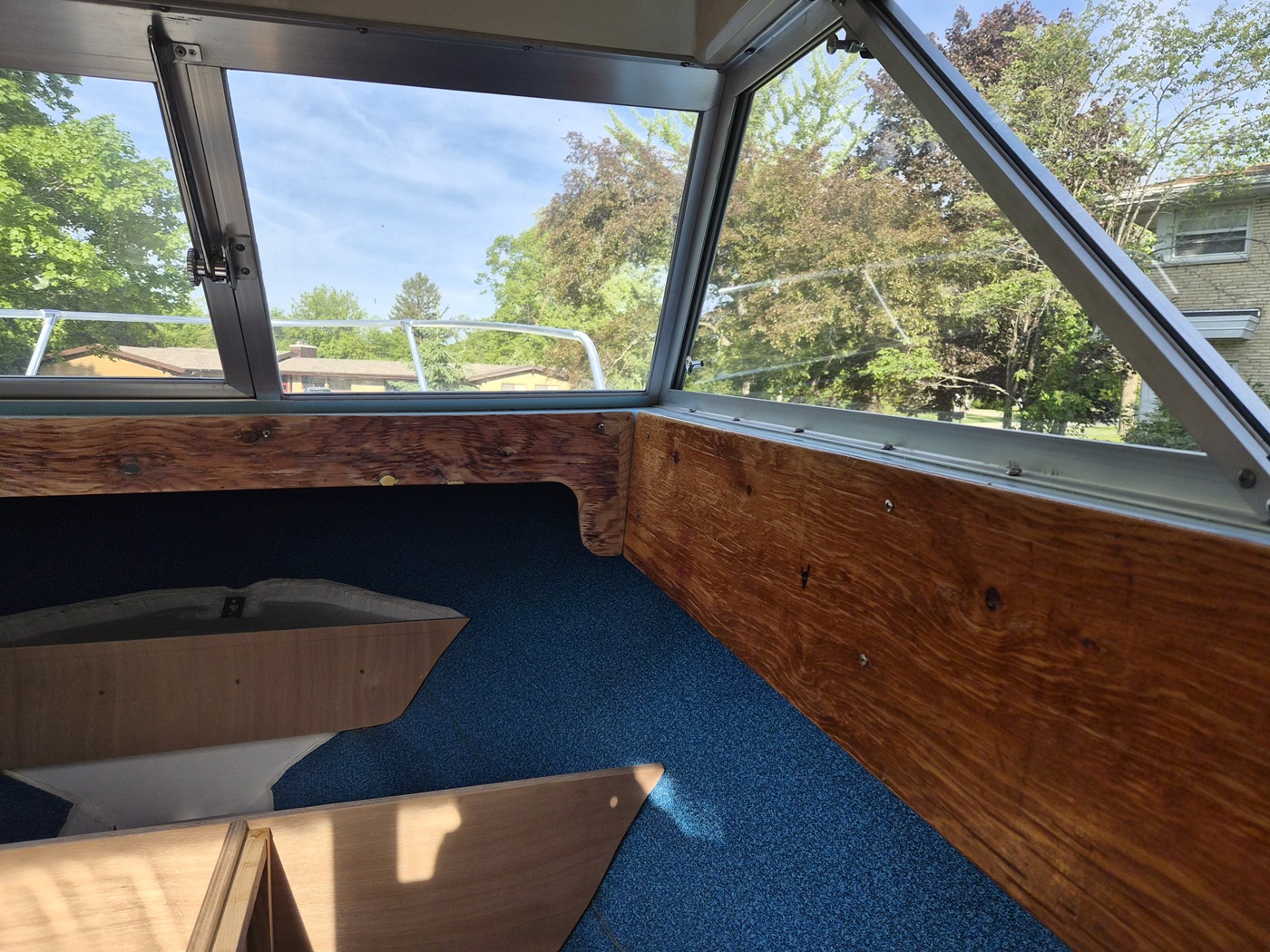
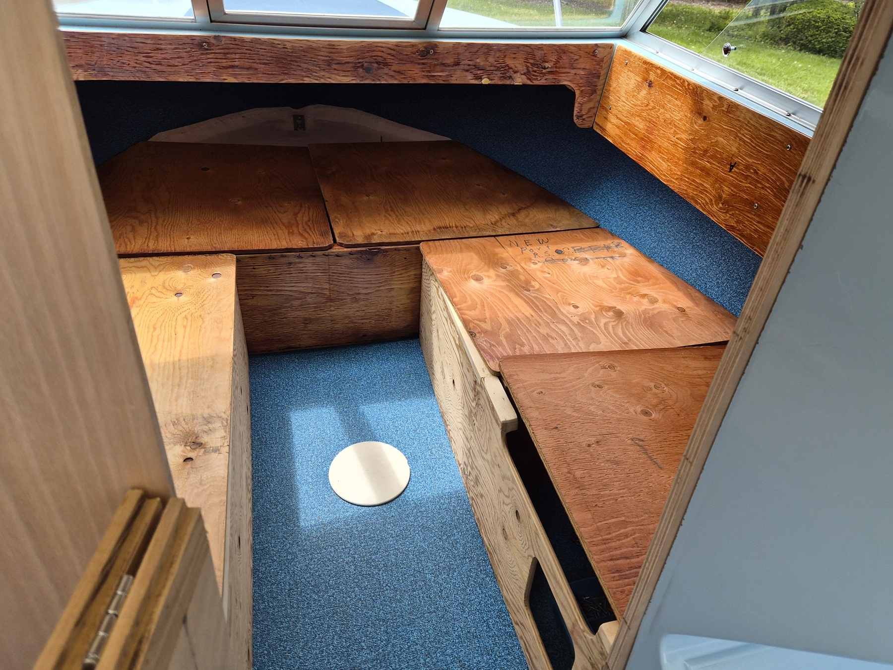
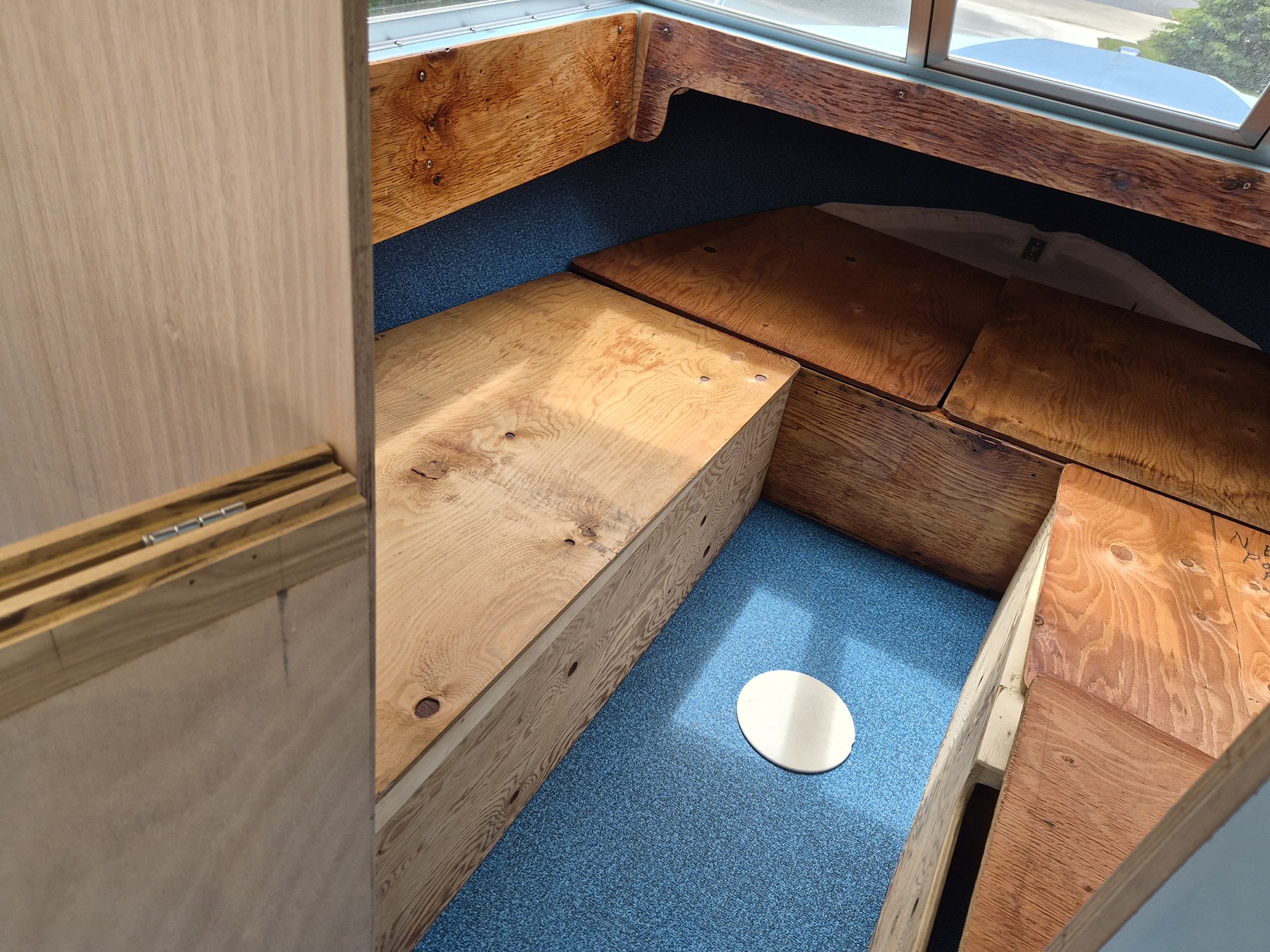
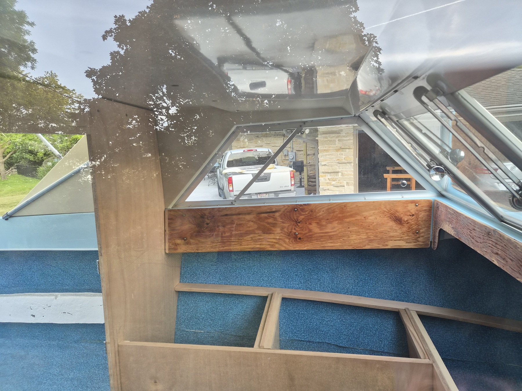
At this point the cabin mockup was complete.
Any other needed work could be completed in the workshop.
My knees will be happier avoiding the numerous trips up and down the ladder.


View through the starboard window.

I will be adding a 1/2-inch by 1/2-inch lip to the hull side edge of each stringer as part of the cushion floor retention system.


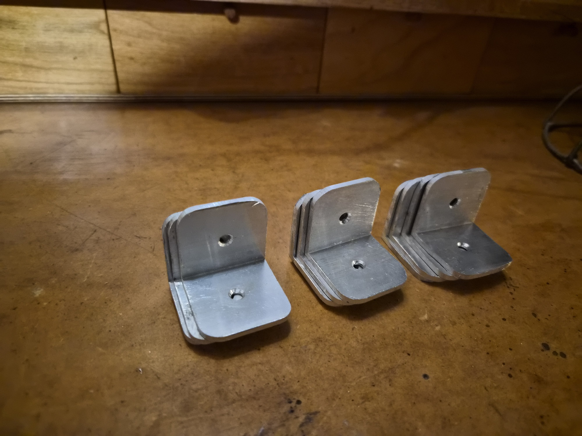
I created twelve 1-1/2 inch by 1-1/2 inch brackets to attach the stingers to the cabin walls, cross-members, and bow floatation foam container.

Twelve chop saw cuts.
Forty-eight edges rounded on the stationary disk sander.
Twenty-four 3/16-inch holes drilled at the drill press.
Forty-eight chamfered hole sides.


All the woodwork was disassembled and returned to the shop for final finishing, leaving boat floor brackets behind. It will be interesting to see what you think of my finish choices.

I will remove the floor brackets temporarily to place 3M 4200 sealant under them prior to final cabin installation.

Please Log in or Create an account to join the conversation.

Time to create page: 9.420 seconds

Donate

Please consider supporting our efforts.

Glassified Ads

FG Login

FiberGoogle

Who's Online

We have 6401 guests and no members online