Welcome, Guest
Username: Password: Remember me

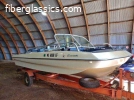
TOPIC: 1971 Glasspar Newport Cruiser - Rejuvenation

1971 Glasspar Newport Cruiser - Rejuvenation 1 year 2 months ago #147532

  • Larsspar
  • Larsspar's Avatar Topic Author
  • Offline
  • Senior Boarder
  • Senior Boarder
  • Posts: 194
  • Karma: 3
  • Thank you received: 17
Been a while since I provided an update.

As of September, my progress nearly ground to a hault.

I've experienced a combination of life events noted by other forum members:
1) eperot and Terrydi....exterior house work, washed windows inside and out, multiple rounds of leaf collection, planters/gardens, storage of bikes, outdoor furniture, flower pots etc
2) Dr. Go's advice on life events popping up
3) per Jimandros, I've come to accept I'm attempting to re-engineer the boat industry
4) Have had to hold down two jobs at work which continues.......

Admittedly the slow down in boat progress depresses me.....I don't think I'll see the water next summer. (not in my own boat anyway)
Still have some updates to share mostly related to outsourced work.

Trailer parts were powder coated in late August by Optimum Coating LLC. Jonathan Maletta and team were able to turn all the 105 parts around in less than a week. Jonathan also caught a typo in the Ivory color I specified in the purchase order, which I was able to correct. Had I receieved light blue fenders back, I'd have been real sad.....


Trailer Slip Tongue fabrication completed by guys at Wisconsin Custom Metal Fabrication Inc. Alfred Bayer and his creaw did a great job!


Had the remaining 5 peiece of plexiglass recreated in tempered glass. Unfortunately, I'll have to make some small modifications to couple of the pieces. Will share this scary exercise when I get to it. The supplied glass is beautiful.


Grew frustrated with my original short block builder and reclaimed my untouched (after 6 months) short block, crank, balancer, flywheel etc, albeit with surface corrosion on the components now. Identified a new partner 90 minutes north of me, Baril Engine Rebuilding, Inc in Green Bay. It's a large operation and Jeff Herlache took great care of me and my components. The job was turned around in 4 -5 weeks, only delayed due to supply chain wait times for new pistons and rods. If you recall, the shattered piston and bent rod had marred the #8 cylinder. They cleaned, inspected, magnufluxed and ultimately bored/honed the cylinders .030 over and resurfaced the block. It looks great and was slipped into the boat storage locker before the weather became bitter.


Built my electroplating station and started zinc electroplating trailer hardware. although a bit tedious, the results are great! (will provide an overview of the process with before/after results soon)


Was able to strip and paint gas tanks, but was disappointed with the paint match received from my paint store. Several shades darker than original. (more on this later)

Biggest diassppointment is/was didn't touch the outdrive components (strip and repaint)

Please Log in or Create an account to join the conversation.

1971 Glasspar Newport Cruiser - Rejuvenation 1 year 2 months ago #147533

You come to Winneconne this summer & you can have a boat ride.
The following user(s) said Thank You: Larsspar

Please Log in or Create an account to join the conversation.

1971 Glasspar Newport Cruiser - Rejuvenation 1 year 2 months ago #147551

  • Dr.Go!
  • Dr.Go!'s Avatar
  • Offline
  • Contributing Member
  • Contributing Member
  • Posts: 1719
  • Karma: 19
  • Thank you received: 125
Sorry to hear of the setbacksā€¦ looks like you are quick to regroup and not let things stop you from your mission. All pictures look great! Keep the faith and even if you hit some boat events without a boat, if we are at the same event, you are welcome aboard.
The following user(s) said Thank You: Larsspar

Please Log in or Create an account to join the conversation.

Dr.Go!

1971 Glasspar Newport Cruiser - Rejuvenation 1 year 1 month ago #147609

  • Larsspar
  • Larsspar's Avatar Topic Author
  • Offline
  • Senior Boarder
  • Senior Boarder
  • Posts: 194
  • Karma: 3
  • Thank you received: 17
Not an exciting boat update but thought some of you might be interested in the electroplating process I'm using to restore my Holsclaw boat trailer hardware. Admittedly, this is time consuming. I've processed 301 pieces so far and find I'm most efficient processing in batches over two-day periods. There are numerous approaches to do this. I found these steps work best for me.

Let's work though this group of trailer jack and hitch plate hardware.
I ran the hardware through a sonic cleaner containing 50/50 Simple Green and water, to degrease the parts. A water rinse and dry left me with this.


I use several different wire wheels and rotary wire brushes to initially strip/clean.


The small rotary bushes are exceptional at cleaning/polishing the inside of nuts, washers, and spacers.


Hardware after the initial wire brush process


The hardware is then hooked on 18 gauge copper wire and lowered into a container of 20% muriatic acid 80% distilled water
This strips the hardware of any remaining plating and corrosion


The hardware is removed and rinsed in a container of distilled water to neutralize the muriatic acid.
The hardware is then set aside to dry. In doing so, light surface rust immediately forms. I let the part dry for 18 to 24 hours.


From this point forward, the parts are handled with lightweight nitrile gloves. One, to prevent the transfer of any oils from my hands to the parts. Two, to protect my skin during the remainder of the plating process.

Back to the wire wheels, the light surface rust is quickly/easily removed, leaving shiny metal behind. The is critical to getting bright, shiny results.

Please Log in or Create an account to join the conversation.

1971 Glasspar Newport Cruiser - Rejuvenation 1 year 1 month ago #147610

  • Larsspar
  • Larsspar's Avatar Topic Author
  • Offline
  • Senior Boarder
  • Senior Boarder
  • Posts: 194
  • Karma: 3
  • Thank you received: 17
Moving on to the plating phase, let's review the plating station layout.
I purchase supplies and follow the zinc plating process developed by Caswell.


The back row of containers performs all the work. The front row are rinse containers for each process.


The metal pot in the upper left corner contains a degreasing solution which I heat to 180 degrees F.


I have the ability to apply both clear/blue and yellow chromate finishes.
All the trailer hardware is being plated using Blue Chromate.


Step1, parts placed in the degreasing solution for 10 minutes.


The parts are removed and rinsed in distilled water.


Step 2, parts are dipped in a 5% muriatic acid bath for 2 -3 seconds and then immediately rinsed in a distilled water bath for several seconds.
This is an etching process.

Step 3, the parts are quickly moved into the plating tank. The plating tank is a busy place.
There is a fish tank aerator in the bottom which keeps the solution moving.
A heater heats the solution to 110 degrees F.
There are two zinc plates (anodes) hung opposed (180 degrees) to one another on the sides of the tank.
Finally, there is a copper pipe that rests across the top of the tank.
Next to the tank is a power supply, (rectifier) that supplies and controls the electrical charge needed to drive the plating process.


One of the Zinc anodes


The anodes receive a positive charge. The copper pipe a negative charge.
The parts are hung from the copper pipe on the 18-gauge copper wire.
The electrical charge strips zinc off the anodes, sends it through the solution and bonds it to the parts.


Caswell provides calculators needed to determine the surface area of the batch of the parts youā€™re plating. The total surface area of all parts, in inches, is then multiplied by .14, which determines how many amps are required for the plating process. This rectifier makes the process easy. The black knob is adjusted until the gauge reads the needed amperage. The voltage is automatically adjusted to support the needed amps. (too much power lead to burning/pittingā€¦not enough, minimal plating) I plate the parts for 20 to 30 minutes, which provides a heavier plating geared towards harsher environments. (Caswell words)


Once the plating is complete, the parts are removed and dipped in a distilled water bath for a copy seconds.
The parts generally have an aluminum like look at this point.

Step 6, the parts are dipped in 5% muriatic acid bath for 2-3 seconds and then rinsed in distilled water.
The parts now have more a shine.


Step 6, soak the parts in bath of Blue Chromate for 40 to 60 seconds.
Rinse in a distilled water bath for a couple seconds.
Hang in a safe place to dry for 12 plus hours.

Please Log in or Create an account to join the conversation.

1971 Glasspar Newport Cruiser - Rejuvenation 1 year 1 month ago #147611

  • Larsspar
  • Larsspar's Avatar Topic Author
  • Offline
  • Senior Boarder
  • Senior Boarder
  • Posts: 194
  • Karma: 3
  • Thank you received: 17
Before and after pictures


Please Log in or Create an account to join the conversation.

1971 Glasspar Newport Cruiser - Rejuvenation 1 year 1 month ago #147650

Larsspar,

You slacker...

Just kidding. Just when I think I'm going to one day restore my Seafair with a high degree of detail, here you go electroplating your own bolts and washers. Simply amazing, and very impressive. I feel like you must sleep an hour a night!

Eric

Please Log in or Create an account to join the conversation.

1971 Glasspar Newport Cruiser - Rejuvenation 11 months 4 weeks ago #147783

  • Dr.Go!
  • Dr.Go!'s Avatar
  • Offline
  • Contributing Member
  • Contributing Member
  • Posts: 1719
  • Karma: 19
  • Thank you received: 125
Great results. Must be very rewarding. I learn so much on this site!
The following user(s) said Thank You: Larsspar

Please Log in or Create an account to join the conversation.

Dr.Go!

1971 Glasspar Newport Cruiser - Rejuvenation 10 months 1 week ago #147926

  • Larsspar
  • Larsspar's Avatar Topic Author
  • Offline
  • Senior Boarder
  • Senior Boarder
  • Posts: 194
  • Karma: 3
  • Thank you received: 17
I'm behind on providing some updates, primarily related to the trailer restoration and cabin window frames and glass.

Let's start with roller pins. (yes, you can question my sanity)

As part of boat trailer restoration, I've seen a number of enthusiasts recommend roller pins be cut and discarded as part of trailer freshening or restoration.
I took an alternate approach to the roller pins and feel the results turned out well. Again....yes..a tedious process.


As a refresher, I used a die grinder and 1/4" burr to grind the flared end off one side of each bunk roller pin while the roller bunks were still attached to the trailer. This allowed me to cleanly disassemble each roller assembly.


Advantages of this approach. The rollers aren't damaged by a cutting process and the roller pins can be re-used.
It appears Holsclaw used some type of hydraulic compression device to press both ends of each roller pin, creating a flare on the end of the pin, which prevents the washers from slipping off the pins while holding the rollers in place


To refurbish the roller pins, I started by taking a scrap piece of hard maple, slightly longer than the roller pins and drilled a 1/2" hole in it, stopping approximately 1/4" from the end of the block


The block was then cut in half, right down the middle of the drilled hole


Using a small chisel, I created a relief for the flared end of the pin in each block


This block is used to hold each pin for the steps executed to machine the pins. (16 total)


Using the block to hold the pins, the first step was to cut off 1/8" of the end of the side of the pin ground down with the die grinder. This provides a clean, square, surface to machine


The block is lightly pressed against the side of the blade teeth and then the saw clamp is set to hold the block tightly. The blade is then turned on resulting in a repeatable, clean, square cut. (16 times)


I used another piece of hard maple and started by drilling a 1/8" through hole. I used the 1/8" hole as a pilot to guide a 1/2" hole 3/4" of the way through the block. The cut end of the pin was pressed in the 1/2" hole till it bottomed out. Then using a hammer and punch, I created centered dimples in the end of each pin. (this wasn't real accurate, but turned out to be close enough)


Using the dimple in the end of each pin as a guide, I drilled a #7 hole, 1 and 1/4" deep in each pin, again using our maple block to hold the pins square


Next, each #7 hole was tapped using a 1/4-20 tap. The block did a good job gripping the pin to prevent it from spinning during the tap process


I procured 1/4"-20 truss head screws and test fitted each pin


Finally, each pin hole was counter sunk for smooth assembly. After 64 cycles, the block was wearing out


As presented previously, pins, washers and truss screws where stripped and zinc plated


This is what the original end of each pin looks like. The flared shoulder prevents the washer and roller from coming off the end of the pin


Each of the original rollers have a thin brass sleeve in them. The threaded end of bolts is hard on these sleeves. By re-using the roller pins, you don't have to worry about the friction and eventual failure caused by bolt threads


I scrubbed each of my rollers in a bath of 50/50 simple green and water. They cleaned up well. This is a mock-up of each assembly


Assembly works as follows: Take a pin and slide a washer down to the flared end. I then applied marine grease only to that 1/3 of the pin and washer. Then carefully slide one roller onto the pin. The tube is Red thread locker which is applied to the threads of each truss screw upon final assembly


The assembly is then slid through the bunk beam and grease applied to the remaining side of the pin. A roller is carefully placed on the pin, washer slipped on next and then 1/4"-20 truss screw with red thread locker applied is screwed in place, completing the assembly. I used a small needle nose vise grips clamped on the flared side of the pin/roller assembly to assist with the trust screw tightening process. The screw side of each assembly will face the inside of the trailer when assembled. I think the final product looks pretty clean........


I've started to assemble sub components in the basement. I think the bunk rollers turned out well.

Please Log in or Create an account to join the conversation.

1971 Glasspar Newport Cruiser - Rejuvenation 10 months 6 days ago #147929

  • Larsspar
  • Larsspar's Avatar Topic Author
  • Offline
  • Senior Boarder
  • Senior Boarder
  • Posts: 194
  • Karma: 3
  • Thank you received: 17
Trailer tongue assembly.....something all boat trailer owners can relate to!
To re-visit, I'm restoring a 1971 Holsclaw C475-20 tandem boat trailer. I've zinc plated most of the hardware in my basement with only the jack roller wheel, two jack tube pieces and 5 keel roller tubes remaining. These remaining pieces don't fit my 3-gallon solution tanks well, so I've been studying what others have done using long narrow tanks. As I sort it out, I'll share in the future.
I've plated 558 nuts, bolts, washers, spacers, covers etc (I have pictures of each batch as proof) Add in the previously mentioned keel rollers and jack components and the total will come to 566 pieces!!


This is what I started with.


The ball coupler housing was disassembled, and powder coated. The hardware was zinc plated in my workshop.


I took this photo to help me remember to the order the ball coupler clamp assembly goes together


Started by assembling the coupler lock trigger. The small stainless spring needs go around the pin/rivet on both sides of the trigger


The trigger and stainless spring were slid up into the handle assembly and the pin pushed through to hold it all in place. Similar to the roller pin post, I drilled and tapped the rivets for this assembly using 10-24 screws. Threadlocker Red is applied to each of the screws, ensuring they will not loosen up unless heated to a high temperature.


Next I pinned/screwed the clamp bolt onto the clamp handle.


The clamp handle bolt is then slipped through the ball coupling housing and a spring, orange clamp plate, square washer, another spring are placed onto the bolt and held in place with a friction fit nut.


Finally, the clamp locator pin (which was drilled/tapped for a 1/4-20 screw) was slid through the assembly to hold the clamp plate (orange piece) in place. The screw, again taking the spot of the formerly peened over portion of the rivet, was put in place with Threadlocker Red applied.


While still on the 'bench', I adjusted the clamp plate (orange piece) nut so it fit my 2" ball hitch properly. The ball is able to pivot smoothly, without any slop and when the clamp handle is released, the ball is able to slide out of the coupler housing without hang-up.


Beauty shot 1


Beauty shot 2 reveals the screws which now fasten the rivets to the assembly in place of the peening process.


When I went to fasten the ball couple housing back on to the trailer tongue, I found the fit to be too snug. I had to use my bolt, washer, nut trick (previously posted to restore the tongue tube to square) to spread the housing open roughly 1/4". This allowed me to tap the housing onto the tongue post without destroying the powder coat finish. The long bolts and safety chains were then tightened in place. Ready for work........

Please Log in or Create an account to join the conversation.

1971 Glasspar Newport Cruiser - Rejuvenation 10 months 5 days ago #147930

The Larsspar Trailer Company would have to charge $10,000 for a simple trailer just to break even.

You can't have fun in a 50 year old cuddy cabin (with a carbureted 302 MerCruiser II drive); What is the matter with you? Maybe I can understand the problems with the II drive? Ballast bags, Monster Tower, Stereo with Blue Tooth, 5 gallon size speakers, a fuel injected big block and of course a $989.00/month for 10 year payment is all a must.

Offer still stands if you want to go boating, just let me know.

Please Log in or Create an account to join the conversation.

1971 Glasspar Newport Cruiser - Rejuvenation 10 months 5 days ago #147931

  • Larsspar
  • Larsspar's Avatar Topic Author
  • Offline
  • Senior Boarder
  • Senior Boarder
  • Posts: 194
  • Karma: 3
  • Thank you received: 17
LOL.....you're on to something! You make a valid point about Larsspar Trailer Co. I'm guessing my dealer lot will be full of unmoved product. The next two posts I publish will really make you think I'm nuts. Still, nearly done with the trailer. Need to finish plating the handful of bigger pieces and then final assembly. The trailer may end up looking better than the boat!!

Please Log in or Create an account to join the conversation.

1971 Glasspar Newport Cruiser - Rejuvenation 10 months 5 days ago #147932

  • Larsspar
  • Larsspar's Avatar Topic Author
  • Offline
  • Senior Boarder
  • Senior Boarder
  • Posts: 194
  • Karma: 3
  • Thank you received: 17
Axles, bearings and electric brakes.
When I first towed home my new to me boat on its matching C-475-20 trailer, I had to cover 600 miles. During the trip from Fort Frances, Canada to Milwaukee, WI, I had to descend into the Duluth/Superior harbor valley. I quickly learned my Nissan Frontier tow vehicle did not have the brakes for this part of the trip. All I can add is I was lucky it was a Sunday morning. I determined I was going to add brakes to the trailer. The rest of the trip was great, the Holsclaw handling some stiff cross winds admirably as we moved along at 70 mph.


Departure from a home on the northside of Rainy Lake, Canada


When I got home I studied the trailer and was happy to see the brake mounting plates on axles. (red arrow) I researched trailer brakes online and based on the 12 inch wheel size, found 7 inch electromagnetic brakes assemblies made by Dexter.
I did look at both the common hydraulic surge brake and electromagnetic brake solutions. I chose the electromagnetic approach for several reasons:
1) ease of installation
2) can control from inside the tow vehicle
3) affordability


After I disassembled the trailer and before powder coating, I mocked up the brakes and determined a couple changes were needed to make the assemblies work.

1) the bearings and seals supplied by Dexter are for 1-1/16th inch axles. The Holsclaw trailer uses 1-inch axles. However, the brake drum outer diameter of the bearings and races are identical to Holsclaw dimensions. Same result for the grease seals. Solution: Use the Timken bearing, race and seal part numbers from original Holsclaw. Worked perfectly.

2)The brake drums were offset slightly too far off the brake backing plates, exposing the brake shoes. As you'll see, it took me a couple of iterations to overcome this issue.


To overcome the brake drum offset, I initially purchased some flat bar from Speedy Metals and machined the four spacer plates on the right. This took me a while to complete and I was happy with my results. I then disassembled the brake assemblies and sent it all off to the Powder Coater with the rest of the trailer.


All components back from the Powder Coater. I purchased new direct Holsclaw replacement bearings, races, and seals.


I polished each axle with strips of 320 grit then 400 grit sandpaper, using a 'shoeshine' motion. The seal surfaces have some minor pitting but cleaned up pretty well.


I reassembled the brakes and then installed them onto the axle brake flanges with the spacer installed, using longer Moser wheel lugs, which were spendy. When I mounted the brake drum, I soon determined the error in my solution.


The brake mounting plates have pins stamped into them. Remarkably, they actually have a purpose. They keep the brake backing plates centered on the axles. My spacers did not guarantee centered brakes.


I removed my carefully machined spacers, placed them in the recycling bin and reinstalled the now centered brakes.

I still had my offset issue to resolve.


Eventually, the light bulb came on as I realized I could get the inside bearing race shoulder machined. A much simpler solution than my crazy spacer approach.


Next challenge, who could help me machine the drums. Milwaukee used to have a machine shop on every corner. Now everything has gone CNC and the shops are devoted to batch production. Not many workers know how to run a classic lathe any longer. In desperation, I contacted my Powder Coat guy. He ended up connecting me with a neighbor of his that has set up a shop at his home. Definitely a good friend to make! A bit blurry, but that is one of the drums in his lathe.


Cleaned up and ready for round two of installation.


I had to completely disassemble the drums for machining. Here, everything is cleaned up and ready for reassembly.


Bearing race installation tool.


When reinstalling the second time, another small problem popped up. The machining increased the gap the axle nut needed to cover. When tightened, the axle nut moved past the cotter pin locking holes in the axle. A quick measure determined a 3/32 inch thrust washer would solve the issue. Obviously, this makes sense as this is roughly the same amount machined off the inside of the brake drum.


Purchased four of these thrust bearing washers from Grainger.


One disappointment: The grease cup O-rings I purchased are not tight enough. When I install the grease cups, they expand out and over the cups. Do any of you have a replacement part number for the O-rings?


Finished product.


Ready for work!


Here are the Dexter part numbers I used. Each carton contained brake assemblies/drums to complete one axle. (right and left sides)

Please Log in or Create an account to join the conversation.

1971 Glasspar Newport Cruiser - Rejuvenation 10 months 4 days ago #147933

  • 63 Sabre
  • 63 Sabre's Avatar
  • Offline
  • Contributing Member
  • Contributing Member
  • Posts: 4676
  • Karma: 147
  • Thank you received: 167
That hill coming down heading south in "Dalute" is a killer even without pulling a trailer. Should stop in Superior to check for burning brake pads :) Drove it many times.

Please Log in or Create an account to join the conversation.

1971 Glasspar Newport Cruiser - Rejuvenation 10 months 4 days ago #147934

I always went Hwy 2 thru Proctor to Hwy 33 to Hwy 53 (or reverse heading to WI) with a trailer in tow. Not only is the hill less horrible but less traffic & stop lights. Will be up there again the 26th.

Please Log in or Create an account to join the conversation.

1971 Glasspar Newport Cruiser - Rejuvenation 9 months 4 weeks ago #147950

  • Larsspar
  • Larsspar's Avatar Topic Author
  • Offline
  • Senior Boarder
  • Senior Boarder
  • Posts: 194
  • Karma: 3
  • Thank you received: 17
Glad to know I'm not alone. With the new trailer brakes, I'll hopefully be ready to safely tackle the decent on my next venture into northern Minnesota.

Springs!
One of the unique features of Holsclaw trailers are the coil springs that provide the baby carriage style ride.

When I disassembled my trailer for powder coating, I also removed the spring clamps from the springs. After studying the photos, I took during disassembly, I realized there's yet again a methodology Holsclaw used to assemble the springs.


I removed the clamps from each spring by rotating them towards the center of the spring. As the distance between the coils gets larger, the clamps just fall out. I used the anvil on my vice and a 2 lb. hammer to straighten the clamps. When they are tightened, they conform to the spring. By straightening them, they will be able to conform to the springs again, when tightened.


The powder coating process worked well on the springs. When heated, the coating flowed into the tight spots in between the spring coils.


There are two types of clamps for each spring. One clamp type has the corner trimmed off. (Red Arrow) These clamps thread into the bottom of the spring. The non trimmed clamps go to the top of the springs.

Related the to springs themselves, on the bottom, the coils are spread apart wider, whereas on the top of the spring, two sets of coils are wound closely together. (green arrow)


I cut four wedges out of hard maple. The wedges help spread the coils to allow me to place the clamps where I want them without damaging the powder coating.


The clamps are placed in the center of the spring and then threaded to each end. The wedges are used to spread the coils inch by inch until the clamp is in its final position.


Side view of finished assembly.


Top view. The spring coils are left proud of the clamps. When the clamps are tightened the gap will be closed as the clamp conforms to the spring.


Final assemblies ready for installation.

Please Log in or Create an account to join the conversation.

1971 Glasspar Newport Cruiser - Rejuvenation 9 months 2 weeks ago #147976

  • Larsspar
  • Larsspar's Avatar Topic Author
  • Offline
  • Senior Boarder
  • Senior Boarder
  • Posts: 194
  • Karma: 3
  • Thank you received: 17
Similar to previous posts I made for restoring the cockpit windscreen, I took the same steps to clean up the cabin wind screen.


Late last summer before putting the boat hull in storage for a long winter nap, you might remember, I removed the cabin top and windows.


The center window was made of plexiglass, and was a bit foggy and heavily set in place with sealant. I'm not sure if this was original, but I chose to have it recreated in tempered (safety) glass.


As done with the cockpit windscreen previously, I pried out all the window seals to separate the glass/plexiglass from the frames.
The center window hinge rivets were drilled out and the frame components all received a good cleaning in a warm bath of simple green and water. Then I gave them a light polish.

The windows seals received the following treatment:
1) Cleaned/scrubbed in a warm bath of simple green and water
2) Soaked in a bath of 30/70 bleach/water for several days, which killed any mold/mildew
3) Exterior seals were lightly scraped with a small paint scraper as needed
4) Exterior seals were rubbed smooth with #00 steel wool soaked in acetone

In the picture above, the seals were put in place with the aid of JB weld RTV grey to fill corner gaps and Permatex Windshield and Glass sealant. This was set aside to dry for a couple days before I came back with razors to rub, trim and scrape excess sealant off the seals and glass


Again, as done previously, the original windows were given a good cleaning with soap and water and then hit with two grades of glass polish, using an automotive buffer.


The center window hinge did need a little flattening, which I was able to perform on my bench vice anvil with a sheet metal hammer. The hinge was reattached using aluminum pop rivets. (as original)


Next, the center window was laid in place and pop rivets applied


The original center window locking hardware cleaned up real nice with a quick rub down using #000 steel wool.


Finished product front and back.

Please Log in or Create an account to join the conversation.

1971 Glasspar Newport Cruiser - Rejuvenation 9 months 2 weeks ago #147977

  • Larsspar
  • Larsspar's Avatar Topic Author
  • Offline
  • Senior Boarder
  • Senior Boarder
  • Posts: 194
  • Karma: 3
  • Thank you received: 17
The cabin side glass was more complicated than I anticipated.


There is a sliding pane and fixed pane in each assembly. A previous owner used hook and latch tape to hold homemade window screens in place. A neat idea that was now showing its age. Removing the adhesive from the window frames required some extra elbow grease.


The side windowpanes were made of plexiglass, some of which were badly scratched. I had each pane recreated in tempered (safety) glass.


A series of screws needed to be removed to disassemble the fixed frame portion of the window.


I stripped one of the screws which I found very frustrating. I should have spent more time scraping adhesive away and perhaps applied a little heat. Using a Dremel cutting disk, I slotted the screw and was able to remove it with a flat head screwdriver.


Once the screws were removed, using a block of wood and soft mallet, I tapped the fixed window free from the frame.


Next, I was able to remove the window frame side channels.


The sliding windowpane still remained trapped inside the frame. It took a little studying, but I soon figured out I needed to flex and twist the bottom window channel (the longest and most flexible piece) past the windowpane and up and out of the channel.


Once the window channel was removed, the sliding window pane came out easily.


Frame disassembled and ready for cleaning.


The fixed window is attached to a bracket using glass setting tape. I tapped the bracket off the windowpane using a soft mallet


Each window channel was lined with 'pile weather stripping', which was failing. A small screwdriver pressed into the weather stripping assisted nicely in sliding the old material out of the window channels.


Windows frames, brackets and channels were all soaked and scrubbed in a warm bath of simple green and water.
The aluminum frames and brackets were all given a light polish and cleaned up pretty well!
Ready for re-assembly!


The original 'pile weather stripping' was a light grey color. I couldn't find any in a similar color on the web, so being the 'Smart Guy' I am, I figured I could buy some darker colored product and bleach it.
Turns out the product I bought is synthetic and in-turn is unphased by the bleach. I had to let this detail go and move on.

Continued in next post.

Please Log in or Create an account to join the conversation.

1971 Glasspar Newport Cruiser - Rejuvenation 9 months 2 weeks ago #147980

  • Larsspar
  • Larsspar's Avatar Topic Author
  • Offline
  • Senior Boarder
  • Senior Boarder
  • Posts: 194
  • Karma: 3
  • Thank you received: 17
Continuing from the last post.


The new 'pile weather stripping' was slid into the slots of each bracket and window channel and trimmed off with a razor.


The thoroughly cleaned side and top window channels were snapped back into place inside the window frame.


The most nerve-racking portion of the assembly was feeding the long bottom window channel strip back into the window frame with the glass in place. It takes a fair amount of pushing and pressure to get the last 6 inches of channel to snap back into the frame. I was worried I would break the glass. Both windows did go back together without issue.


Each sliding side window has a hole drilled in it to house the knob used to slide the window back and forth. The glass shop I worked with had the hole drilled to 1/4 inch. This was too small. I needed a 19/64th-inch hole for the knob grommet to fit properly. The shop claimed holes could only be drilled in 1/8th-inch increments. To make matters more interesting, the holes are drilled 'before' the tempering process takes place. I chose to try and correct this delicate situation myself. Glass does not like to be modified after it's been tempered. I learned this first hand when trying to grind 1/16-inch off a piece of cockpit side glass. I did successfully grind it, but when I removed the tape, I had applied to prevent scratching the face of the glass, it became unstable and exploded in the hands.

I needed to enlarge the hole 3/64-inch which didn't seem to be too much. I took a 1/4-inch wood dowel and cut a slot in it straight now the middle. I then slipped strips of 320 grit sandpaper in the slot and wrapped it around the dowel.


The dowel with sandpaper wrapped around it was slowly fed in and back out of the hole. Strip lengths were increased (making the dowel larger) until the hole grew to 19/64-inch diameter.


I went slow and kept the glass cool and ultimately achieved success! These larger pieces of glass were not cheap!


Moving on to the fixed window, I needed to find new Glass Setting tape. Studying the web, I learned how to properly size the required tape thickness. I used a machinist caliper to measure the inside dimensions of the bracket channel as well as the thickness of the glass. I subtracted the glass thickness from the bracket channel width and added 1/64 inch to the result. I ended purchasing from Bob Drake as they offered the tape in thicknesses that varied by 1/64th inch. (I needed 3/64-inch thickness tape)


I used the glass to size the required length of tape and cut it with some scissors.


I then folded the tape evenly over both sides of the glass to create a crease in the tape to aid with assembly.


The tape was then wetted with a mix of warm water and Dawn dish soap.


The tape was placed back on the glass.


The bracket was then pressed onto the tape/glass. The rubber mallet was then used to tap the bracket down flush with the glass. As an inexperienced person, I was worried I would break the glass when striking the bracket. The glass proved to be very durable and I was able to fully seat the glass/tape to the bottom of the channel. Without the correct tape thickness, I could see this getting very frustrating.


Any excess tape was trimmed away with a razor knife.


The fixed frame glass was then cleaned and installed into the window frame. Once the holes were lined up, the screws securing the backet to the window frame were reinstalled.


Inside finished assembly with knob cleaned, polished, and installed.


Exterior view of completed assemblies.


I have one remaining problem to resolve. This thumb screw originally had a rubber stopper on the end. The thumb screw presses against the sliding window to hold it in a desired position. As the rubber foot wore away, the metal started to deeply gouge the plexiglass sliding window.

I'm looking for ideas repair ideas. I'm thinking I could drill and tap the thumb screw for a small appliance foot, but I haven't found the right small size yet.

If you have any ideas, please share.

Please Log in or Create an account to join the conversation.

1971 Glasspar Newport Cruiser - Rejuvenation 9 months 2 weeks ago #147983

for your rubber stopper, couldn't you remove the old pieces, clean up the ends of the thumb screw and use automotive vacuum caps of appropriate size? Super cheap to buy a handful to keep around as they wore out. I would imagine you would only need to trim them down in length to fit for this application.

Attachments:
The following user(s) said Thank You: Larsspar

Please Log in or Create an account to join the conversation.

1971 Glasspar Newport Cruiser - Rejuvenation 9 months 2 weeks ago #147984

have you ever poked around in mcmaster.com ?
The following user(s) said Thank You: Larsspar

Please Log in or Create an account to join the conversation.

1971 Glasspar Newport Cruiser - Rejuvenation 9 months 2 weeks ago #147985

  • Larsspar
  • Larsspar's Avatar Topic Author
  • Offline
  • Senior Boarder
  • Senior Boarder
  • Posts: 194
  • Karma: 3
  • Thank you received: 17
Thanks for the good idea Lenny. If I can find one with a flat end....it might work.
Two things I'll have to check: 1) The distance between the glass and the thumb screw bracket. (determines how much plug I can thread on the screw. 2) A way to stop the thumb screw from having the ability to back out to a point where the plug falls off.

Chuck, I have purchased from McMaster Carr previosly, but hadn't considered shopping there for this. Good idea! I'll give their site a look.

Please Log in or Create an account to join the conversation.

1971 Glasspar Newport Cruiser - Rejuvenation 9 months 2 weeks ago #147987

1. you could put a little bit of silicone inside to increase the thickness of the end if needed, this will also help keep it in place.

2, see answer 1. This should "Glue" it in place so when the screw is backed out and touching the cap, it should stop it from turning any further.

Edit: I looked at the website recommended above. If your old foot pad unscrews from the thumb screw, they have plenty to choose from.
The following user(s) said Thank You: Larsspar

Please Log in or Create an account to join the conversation.

1971 Glasspar Newport Cruiser - Rejuvenation 8 months 2 weeks ago #148105

  • Larsspar
  • Larsspar's Avatar Topic Author
  • Offline
  • Senior Boarder
  • Senior Boarder
  • Posts: 194
  • Karma: 3
  • Thank you received: 17
It's finally time to begin assembly of the BOAT TRAILER!! I've been looking forward to this for months!!
This is a detailed post of the assembly of the trucks.


Earlier this year I posted the assembly of the axles in my basement. I moved them to the garage floor along with wheels/tires and all the original hardware I plated over the winter.


Started by attaching the axle link mounting plates. The original bolts and interference/friction fit nuts. There is a shock bolt laying perpendicular to the bracket on the right. I used that to align the bracket on the right during assembly


Correct mounting has nuts to the inside of the assemblies


Next layed out the spring assemblies and bolts, washers, and lock washers


When I disassembled the trailer, the spring plates had orange sealant under them, likely as a way to keep water out of the axles when they're dunked into the water. Modern day Orange RTV is for high temp applications like exhaust. Instead, I chose Grey RTV which is designed for heavy vibration applications. I also applied Red Thread Locker to the lower (axle side) spring plate mount bolts


Grey RTV applied to both top and bottom of the axles


Reminder from previous post, the spring plates with the corner trimmed off, attach to the axles


Spring attachment to the axles complete. This was more difficult than I imagined. I needed to use a large vise grips to hold the spring plates while tightening the bolts. This marred the corners of the spring plates including my beautiful powder coating. Very frustrating.......... I should have chased the spring plates with a tap first. Tough lesson learned


Next, focused on the links that connect the axles together


I pressed the replated bolt sleeves into new rubber washers. The other half of the bolt sleeve slips nicely into the axle link ends


The beauty of this design is you can't overtighen the bolts and interfence nuts (crushing the washer) because the sleeves act as governors. It also allows the links to pivot independently with little friction


Links fully attached to axles. Again, all nuts face to inside of trailer


Next up were the frame cross mounts which sit on top the springs. The frame then lays on and bolts to these cross mounts. Bob M has mentioned seeing thin rubber membranes between the springs and crossmounts on other trailers, perhaps to alleviate sqeaking. I chose to place RTV Grey on the top spring plates prior laying the crossmounts in place. I also chased the top spring plates with a tap prior to installation, which made tightening the bolts much easier


Cross mounts complete, which include the fender bracket mount supports


Next I mounted the panhard or anti-sway bars. The bolts were mounted so the nuts face the back of the trailer. The same rubber washers and bolt/interference nut combination are used throughout the trailer


Panhard bar installation complete


Axle assembly complete


Wheels/tires mounted


Took the time to retorque/set the wheel bearing nuts and also adjust the brake shoes. Next up, mount the frame, lighting and wiring

Please Log in or Create an account to join the conversation.

1971 Glasspar Newport Cruiser - Rejuvenation 8 months 2 weeks ago #148108

Man, you'd better hold on the the trailer your boat currently sits on and use that because I wouldn't want the one you are restoring to come anywhere NEAR water when you are done. Way too nice now.

Nice lawn tractor, BTW. Oldie but a goodie.

Eric

Please Log in or Create an account to join the conversation.

1971 Glasspar Newport Cruiser - Rejuvenation 8 months 2 weeks ago #148116

  • Larsspar
  • Larsspar's Avatar Topic Author
  • Offline
  • Senior Boarder
  • Senior Boarder
  • Posts: 194
  • Karma: 3
  • Thank you received: 17
Thanks Eric!

This is the only trailer I own. The boat is in a storage locker quietly waiting for the trailer.


Love Bolens tractors. They were manufactured 20 minutes north of where I live. I have two of the Tube Frame models and many attachments. The one you saw is a 1972 1556. It cuts to lawn, tills the soil, vacuums leaves and debris, thatches, sprays the weeds, throws and plows the snow. It get's used year round!
Attachments:

Please Log in or Create an account to join the conversation.

1971 Glasspar Newport Cruiser - Rejuvenation 7 months 1 week ago #148286

  • Larsspar
  • Larsspar's Avatar Topic Author
  • Offline
  • Senior Boarder
  • Senior Boarder
  • Posts: 194
  • Karma: 3
  • Thank you received: 17
Continue to assemble the Holsclaw trailer. Installation of the frame on the trucks and the temporary installation/test fit of the slip tongue.


The frame to truck brackets are attached to the trucks with a long bolt which slips inside a sleeve. The sleeve prevents the cross member from bending/crushing as the nut and bolt are tighted. I brushed a layer of marin greese on the bolts prior to installation. (corrosion prevention measure)


Bracket installation complete


Went to the storage locker and collected the frame. It's a little longer than the bed of my truck.


The frame is bolted to the brackets with same size bolts and interference nuts used throughout the trailer


Frame installed


Next, installed the drag links. Same rubber washers used on the trucks are used as insullators between the drag link and the frame


Correct assembly


Drag links are bolted directly to the trucks


Installed with the drag link and nuts to the inside of the trailer


Truck to frame installation complete


Next installed the cross members that support the roller bunks


Reveresed the screw side of a wood clamp, turning it into a spreader. This allowed me to put the roller bunk cross memeber in place without marring the frame finish.


Rear roller bunk cross member installed


The front roller bunk cross member is attached with large u-bolts. They replated very nicely!


There were some very subtle depressions left in the frame from when the u-bolts were originally installed. This helped make re-installation alignment easier. Everything else installed up to this point used exisitng holes as reference points.


Added the tail light/license plate brackects next.


They install inside the foward portion of the rear roller bunk cross member


Tail light/license plate brackects complete.

continued in the next post

Please Log in or Create an account to join the conversation.

1971 Glasspar Newport Cruiser - Rejuvenation 7 months 1 week ago #148287

  • Larsspar
  • Larsspar's Avatar Topic Author
  • Offline
  • Senior Boarder
  • Senior Boarder
  • Posts: 194
  • Karma: 3
  • Thank you received: 17
Continued frame on trucks assembly


Next made a run at the fender support brackets.


Tight installation quarters


Fender support brackets complete


Temporarily installed the tongue beam. It's too long to fit in my garage, so final installation won't occur until I'm ready to put the boat back on the trailer. Doing temporary assembly allowed me to mock up my wiring harness.


Tongue attachment nut/bolt and the tilt mechanism pin. Again, both plated very nicely.


There is a key hole the tilt mechanism pin fits through.


Tilt mechanism installed and locked. There is a bend in the pin which acts as a locking cam. When the pin handle is twisted down, the cam presses against the frame bracket, keeping both the tongue beam and frame pressed tightly together.


Last step today was to slide in the slip tongue.


Partially inserted.

What I like about this approach
1) space savings
2) maintains original look
3) Security measure - by removing the tongue, it makes it much harder to steal. (not impossible)


Two 5/8" pins hold the two pieces together during use.


I have since added a couple washers and plated the pins/cotter pins and washers.


Picked up this locking hitch pin to replace one of the pin/cotter pin assemblies.

Please Log in or Create an account to join the conversation.

1971 Glasspar Newport Cruiser - Rejuvenation 7 months 1 week ago #148288

  • Larsspar
  • Larsspar's Avatar Topic Author
  • Offline
  • Senior Boarder
  • Senior Boarder
  • Posts: 194
  • Karma: 3
  • Thank you received: 17
Worked on the original shock absorbers. I again learned there are a few very important hardware related things to observe when setting shocks up on our Holsclaw trailers.


The original MAECO 18707s still had some rebound left in them, so I chose to re-use them. As posted previously, I stripped and replated all the shock hardware over the winter.


All original shock hardware after replating process. Quite a few pieces.


Into the media blast cabinet they went.


The shocks as provided by MAECO were a darker blue than the trailer. I did my best to match the original color, but admittedly, the Rust-Oleum Navy Blue is a little lighter and doesn't have the metalic look the original color does. Still it proved to be fairly close. I still don't understand how to use the Rust-Oleum 'Clean Metal Primer'. You're supposed to spray it on lightly and then either top coat within an hour or wait 48 hours. I always try to top coat within an hour and am always disappointed by some spot of primer that is still not dry due to heavy build. This then leads to top coat runs, or primer bleading through the top coat. Wish I could get them powder coated, but they will not stand the heat of the curing process.


Painting complete and cured for 72 hours. Paint was still a little soft so they were handled with care. Prior to painting, they were dusted off with compressed air. Once the paint cured, I also rinsed them with water good, to ensure any remaining grit inside the upper sleeve was washed away.


The original rubber bushings were disintegrating. Replacement on the right.


I found direct 5/8" hour glass polyeurethane replacements from Energy Suspension. (9.8107G) They fit perfectly.


Just prior to assembly, I dropped the new bushings into a bucket of warm water and Dawn dish soap.


The soaked and now slippery bushings were easily tapped into the shock eyes with a firm swing of the soft mallet.


Next, the shock bolt sleeves were placed in the soapy water bucket and then driven into the shock bushing with the soft mallet.


In its uncompressed form, the shock bushing is wider than the shock bolt sleeve. I used a 7/16" long socket to center the shock bolt sleeves in the shock bushings.


Ready for installation on the trailer.


Okay, this is where you have to pay close attention. Addtionally, for those that are quick to discard the original hardware, I'm not sure how you find all the correct pieces. Recently, I was able to purchase dealer literature for my trailer from eBay. This is the Holsclaw provided shock assembly schematic.


Nuts in the red circle are placed on the inner and outer sides of the lower (axle) bracket. (they are thinner)

Nuts in the green circle are placed in the inner side of the upper (cross member) bracket.

Nuts in the blue circle are placed on the outside of the uppder (cross member) bracket. They are interference fit nuts.

Finally, the concave side of the washers face away from the bushings. Many believe the concave side of the washer should face the bushing, covering it. The concave side of the washer faces out, so the bushing can twist and flex laterally as the suspension moves up and down.


Bolts, washers and inside nuts installed on the uppers and lowers of each shock. I covered each bolt with marine grease prior to assembley as addtional effort to slow corrosion where the bolt and sleeve contact one another.


The nuts/bolts were tightened until the washers seated against the bolt sleeves inside the bushings. This slightly compresses the bushings.


Upper and lower nuts and lock washers ready for installation on the trailer.


There is space on the top shock mount for the thicker nuts.


The thinner nuts are a necessity on the lower mounts. There is't enough space for thicker standard nuts.


Installation complete!

Please Log in or Create an account to join the conversation.

1971 Glasspar Newport Cruiser - Rejuvenation 7 months 1 week ago #148289

  • Larsspar
  • Larsspar's Avatar Topic Author
  • Offline
  • Senior Boarder
  • Senior Boarder
  • Posts: 194
  • Karma: 3
  • Thank you received: 17
More than you may want to know about 52 year old tail lights. I appreciate many find it easier just to replace worn out lights with modern LED fixtures. The investment is minimal. I like the look of the original lights and chose to try and restore them.


Starting point. Grote 469 housings with Grote 471 rear and Grote 468 side lenses


The driver's side housing has an opening in it to shine light on the trailer license plate. I still need to figure out how to make a replacement window for it


I carefully pulled the wires into the housings and through the bulb socket housings


Using a small block of wood, I tapped the mounting scews through the back of the housing


Just took some light taps


Housings disassembled


The trailer was originally wired with 3 bond wire. I chose to use 4 bond wire as i plan to run ground wires direct to each fixture as opposed to relying on the trailer as a ground


I replated all the hardware including the springs. The light sockets are brass which are pressed into zinc plated steel mounting plates. The electical components were zinc plated and finished with yellow chromate. (as original) The lense screws were zinc plated and finished with blue chromate


When your significant other isn't looking, slip the housings and lenses into the dish washer. It's amazing how clean they can get


The tops of each light housing are a bit sun burned


I saw this trick online to refresh weathered plastic. My results were mixed. You have to be careful not to get the plastic too hot, but warm enough the plastic gets soft. My results restored the original color but also led to some minor blistering


I polished the housings and the lenses with PlastX. This did a nice job removing any hazing and minor scratches. Each piece seemed to brighten up


Reassembled the side marker light assemblies. Spring goes over the wire and the wire is threaded through the hole in the bottom of the bulb socket


Quick test


The side marker fixture slides through a slot in the housing. One of the studs holds it in place once they're re-installed


The side marker wire goes through a hole in the housing where it joins with the other socket wiring


The main bulb socket controls a dual filament bulb that performs the role of marker, blinker and brake light, The bulb socket has a groove in it and the wiring base has a tab on it.
The wire closest to the tab is for the blinker/brake filament. The other wire is for the marker filament.


The light bulb contacts the brass buttons in the bulb socket.

Please Log in or Create an account to join the conversation.

1971 Glasspar Newport Cruiser - Rejuvenation 7 months 1 week ago #148290

  • Larsspar
  • Larsspar's Avatar Topic Author
  • Offline
  • Senior Boarder
  • Senior Boarder
  • Posts: 194
  • Karma: 3
  • Thank you received: 17
Continuing the light restoration


My method to replace the wiring was to cut the wires 1/4 inch from where they attached to the brass buttons and remove the wire insulation


I stripped the new feed wire in the same fashion and then pressed the wires into one another so they fit together


I then laid the assembly on a soldering iron and once hot enough, applied solder to the bundle. This forms a strong, conductive, bond


All the wires for both housings including the additional ground wires were soldered and then had heat shrink applied (black boots) to insulate them. The wire colors used correspond with industry standard trailer wiring diagrams. (brown = marker, white = ground etc) Sorry for the blurry pictures.......


The wires/buttons were threaded back through the appropriate hole in the plastic socket bases, through the replated springs and finally through the bulb sockets


Placed some dialectric greese on each socket base and interior socket walls to prevent corrosion. Notice the tab on the base aligns with the slot in the bulb socket


Next, the sockets were placed in the housings and the studs were pressed back through the socket brackets and out the back of the housings


The side marker light wire and the tail light marker wires are joined in a square wire holder inside the housing. A clip with two reliefs in it (one for each wire) is pressed into a slot in the square wire holder. In doing so, each wire's insulation is pierced, joining the wires together


Wire clip installed and wires routed under the bulb socket and through holes in the back of the housing


Test - both marker and brake/blinker circuits work well


Installed replated lense screws and mounting lock washers and nuts


Test with lenses in place


Finished assembly mounted with added ground wire attached directly to the outside mounting stud.

Next up, trailer wiring saga.......not my forte.....

Please Log in or Create an account to join the conversation.

1971 Glasspar Newport Cruiser - Rejuvenation 7 months 1 week ago #148291

  • Larsspar
  • Larsspar's Avatar Topic Author
  • Offline
  • Senior Boarder
  • Senior Boarder
  • Posts: 194
  • Karma: 3
  • Thank you received: 17
Completed what I see as the most tedious part of the trailer assembly, wiring. I understand there are much more efficient ways to complete the task. I chose the route that I believe will last the longest. I think the results turned out fairly clean and should be reliable for years to come.


Before I even started wiring,
I took a detour in search of these factory wiring clips. I couldn't find any, so, I set out to make some. I needed 12 in fact, to support the wiring loom for the newly added electric brakes. I used some card stock to make a template of the original clip shown here


I purchased a small 16 gauge plate at my local box store. Using a jig jaw, the edge of a work table, a couple clamps and a piece of dead straight hardwood, I cut 12 strips of metal to the length of my template


Some time at the drill press to make the holes and the bench grinder to round the corners helped me get to this point


Using a jig and a drill bit, I attempted to form the u-shaped portion of each clip. I ended up with some creases as opposed to round channels. Next, I clamped a rounded chisel into a vise and using a hammer, further shaped the u-shaped bend. I give myself a C+. I drilled my drip holes for the u-shaped channels in the wrong place and my u-shaped channels are not as smooth as the stamped factory pieces. Still, after plating, they look the part


Because I added electric brakes, I needed to upgrade from a 4 pin connector to a 7 pin connector. I shopped around for a while looking for a long enough 7 pin cable, and eventually found this 15 foot one. Many of the other cables available are only 8 - 10 feet long, which worried me, because this trailer has a very long tongue


First thing I did was plug the cable into my truck and test each wire for its function.


I printed out a standard 7 pin wire diagram I found on the internet and used it as a worksheet


I'm glad I did this, because although my Chinese cable does seem well made, none of the wire colors corresponded to standard trailer wire harness colors


I hooked the trailer up to my truck and pushed the cable through the trailer tongue. Because the cable is so thick, it's fairly rigid, which made it easy to push through the tongue. I then held my breathe and drill two holes in the trailer for screws that attached the cable clamps to the trailer.


I used Curt 4-bond wire for all lighting duties


I purchased a spool of 12 gauge 2-bond wire for the trailer brakes


Several sizes of heat shrink tubing were used to shroud solder joints and for the brake wiring, add an extra layer of protection and strength

Please Log in or Create an account to join the conversation.

1971 Glasspar Newport Cruiser - Rejuvenation 7 months 1 week ago #148292

  • Larsspar
  • Larsspar's Avatar Topic Author
  • Offline
  • Senior Boarder
  • Senior Boarder
  • Posts: 194
  • Karma: 3
  • Thank you received: 17
Continuing the trailer wiring


Rather than using solderless connectors, I chose to solder all my connections together. This style connection was the easiest.


You slide the wires into one another and then solder them together. Don't forget to slide your heat shrink boots on before you solder the joints


There were several solder joints that are more complex. For both electric brake wiring and running light/ground wiring, I had both 'T' and 'X' joins to make. I started by carefully splitting the bonded cable with a razor knife. Try not to pierce the insulation of either wire


Then using a wire insulation cutter, make two cuts, 1/2 inch apart


Use a razor knife to trim the wire insulation laterally


Peel the insulation off and you're left with exposed, but unbroken wire


For a 'T' joint, wrap the exposed end of a wire around and solder


For an 'X' joint, strip the insulation from the middle of both wires


Wrap the exposed portion of one wire around the exposed portion of the other wire and solder


As it's not possible to use shrink tube to insulate 'T' and 'X' joints, I apply 5 or 6 coats of Liquid Electrical Tape as directed on the can


Once dry, the finshed product looks like this. I then carefully wrapped the individual wires first, then the bundled wires with electical tape for added strength


I thought about using one of these junction boxes to join the 7 pin plug cable to the trailer wiring harness, but decided against it because I figured it would be a water trap on a boat trailer


I then wrapped the all the connections with electrical tape for added protection and strength, keeping the wires bundled together


The 4 bond wire slipped nicely into the factory, welded on, wire clips. I zip-tied the 2 bond brake wire to the 4 bond lighting wiring . This and the remaining pics show the results. Everything has tested perfectly


Ground and running light wires needed 'T' connections at the back of the trailer


Long lengths of Heat shrink were applied to the brake wires as a protective layer


I ran heat shrink up through the tail light brackets to protect the wires from chafing


shot of the clips holding the brake wires


One or two posts on final trailer assembly
One post on dialing in the electric brakes

I'm anxious to get this done so I can get some boat work done yet this summer!

Please Log in or Create an account to join the conversation.

1971 Glasspar Newport Cruiser - Rejuvenation 7 months 6 days ago #148296

Trailer is looking so nice I would hate to see it used and get a speck of road dirt on it.
The following user(s) said Thank You: Larsspar

Please Log in or Create an account to join the conversation.

1971 Glasspar Newport Cruiser - Rejuvenation 7 months 6 days ago #148297

  • Larsspar
  • Larsspar's Avatar Topic Author
  • Offline
  • Senior Boarder
  • Senior Boarder
  • Posts: 194
  • Karma: 3
  • Thank you received: 17
I hear you Lenny.
Somehow you found the courage to use your beautiful boat and seem to be enjoying it immensely. I hope my boat turns out as nicely as yours! I have a couple more posts documenting the finish of the trailer. I'm happy with the way the it turned out and pleased the boat rolls so much easier on the trailer.

Please Log in or Create an account to join the conversation.

1971 Glasspar Newport Cruiser - Rejuvenation 6 months 4 weeks ago #148324

  • Larsspar
  • Larsspar's Avatar Topic Author
  • Offline
  • Senior Boarder
  • Senior Boarder
  • Posts: 194
  • Karma: 3
  • Thank you received: 17
Picking up from where we left off with assembly of my 1971 C-475-20 boat trailer. I apologize up front, as there are so many components involved in this post, you may find my captions confusing.


Here are the keel and stern/transom roller components. All the hardware was replated and the brackets powder coated


Three of five keel rollers attach to square tubing cross members that are welded in and make up the greater frame. When reinstalling the roller u-bolts, placement was made easier by feeling for and identifying the witness marks left behind when the u-bolts were originally installed (red circles). The other two keel rollers are bolted through holes in the roll bunk cross members which make them easy to index


Hardware for three of the five keel rollers which mount to the square tubes


Each keel roller tube was brushed with marine grease.


The keel roller tube is slid through the left side of the keel roller bracket, the keel roller and finally out the right side of the keel roller bracket. The tube held in place by a simple cotter pin which slips through holes in the keel roller tube. The hardware pictured is for keel rollers that attach to the roller bunk cross members. The give away is the two metal spacers pictured inside the u-bolts


Two keel rollers attach through holes in roller bunk cross members. The roller bunk cross members are u-shaped and can be pinched together when tightening the u-bolts. (the open portion of the roller bunk frame face down) The spacer pictured slips into the the open portion of the u-shaped roller bunk frame and then the u-bolt is slid through the front side of the u-shaped roller bunk frame, then the spacer and out the back side of the u-shaped roller bunk frame. When the u-bolt is tightened, the spacer prevents the u-shaped roller bunk frame from being pinched together


Applied marine grease to the portion of the u-bolts that slide through the roller bunk frame spacers


Five large keel rollers and one smaller bow roller installed


Close up of the bow roller installation. It bolts to a small trailer frame cross member which has four holes drilled in it, so, placement is easy


The stern/transom roller consists of a bracket, 3 rollers, two washers, long bolt, and an interference nut. The nut/bolt are tighted just enough to place slight drag on the rollers when they spin. The brackets are unique to both right and left hand (port and starboard) sides of the trailer. A 'notch' is stamped into each bracket, that when properly installed, prevents the rollers from tipping to far to the inside of the trailer


The roller assembly is then bolted to a small bracket which in turn bolts to the back of the trailer frame


Another view of how the stern/transom roller is attached to the rear of the trailer. All 3/8" hardware


Stern/transom rollers installed


Bunk roller brackets and hardware


The bunk rollers can be adjusted up and down via a large bolt which rests on a domed foot. The domed foot was originally held in place by a tack, two of which I broke during disassembly. As suggested by Donald Diers, I tapped the hole in the end of the adjustment bolt for a screw as a replacement for the nail. (all hardware pictured)


Adjustment bolt and lock nuck installed


Domed foot held onto the end of the adjustment bolt by the screw, screwed into the end of the adjustment bolt with some red loctite applied


The hardware pictured is used to attach the bunk roller adjustment bracket to the frame bunk roller cross member. 3/8" hardware


Bunk roller adjustment bracket bolted in place using the two long bolt nut combinations. There are four bunk roller adjustment bracket assemblies

(continued in next post)

Please Log in or Create an account to join the conversation.

1971 Glasspar Newport Cruiser - Rejuvenation 6 months 4 weeks ago #148325

  • Larsspar
  • Larsspar's Avatar Topic Author
  • Offline
  • Senior Boarder
  • Senior Boarder
  • Posts: 194
  • Karma: 3
  • Thank you received: 17
Continuing with roller and fender installation


Next came the brackets that attach the bunk roller assembly to the bunk roller height adjustment brackets. Again, a spacer is used to prevent the u-shaped bracket from getting pinched as the nut/bolt is tightened. There are four sets of this assembly. 3/8" hardware


Good view of the spacer installation


Top view of the the bunk roller attachement bracket installation


The bunk roller assemblies are fastened to the bunk roller attachment brackets via a simple 3/8" bolt and interference nut


One bunk roller assembly installed


Fenders and mounting hardware. Again, hardware replated over the winter. 3/8" bolts/interference nuts


Bolted easily to the previously installed fender brackets


Rollers and fenders installed!


Took a piece of 1/8" by 1" flat bar and bent the end 90 degrees in the vice


Trimmed the flat bar and welded it to a large 1/2" washer, drilled a 1/2" hole through the bar and then plated everything


Bolted it to an exiting hole behind the ball mount hitch plate. It will hold/support my trailer wire harness cable/plug


Side view of finished product


In action


Pop riveted the original identification plate back in place


I can live with the patina. The other plate which attaches to the winch post is being replicated currently via a Donald Diers connection. Thanks to Donald

Will assemble the windpost in the next post

Please Log in or Create an account to join the conversation.

1971 Glasspar Newport Cruiser - Rejuvenation 6 months 4 weeks ago #148326

  • Larsspar
  • Larsspar's Avatar Topic Author
  • Offline
  • Senior Boarder
  • Senior Boarder
  • Posts: 194
  • Karma: 3
  • Thank you received: 17
Winch stand assembly


Schematic of the winch stand assembly


Winch stand brackets and hardware. The winch straps are very popular and have many advantages over steel cable or nylon rope. Still, I may return to nylon rope so I can use the patented Holsclaw securing hooks/method


Winchpost bolted to the trailer tongue beam. Position will need to be adjusted once boat put on trailer


I wrapped my rubber bow pads/snubbers in duct tape in an attempt to keep them from failing. Consider the way the trailer is designed. The keel/hull of the boat is supported by rollers and frame riding on the wonderful coil spring trucks.
The bow of the boat however, rests on the pads/snubbers which bolt directly to the rigid winch post. The pads/snubbers take a beating because they are the only form of shock absorption for the bow of the boat. Members of a Facebook group devoted to Holsclaw trailers are working in reproductions


Port side of the assembly


Top view of the bow pads/snubbers assembly


Close up view of the bow pads/snubbers


Starboard side of winch post assembly


Revisiting a previous post, stripped and plated pins, washers and keys that hold the slip tongue in place. Gave the same treatment to some remaining wire loom brackets


In place


Wrap-up for the night. Next update...finishing details and review of the electric brake controller and brake controller adjustment

Please Log in or Create an account to join the conversation.

1971 Glasspar Newport Cruiser - Rejuvenation 6 months 4 weeks ago #148327

  • Larsspar
  • Larsspar's Avatar Topic Author
  • Offline
  • Senior Boarder
  • Senior Boarder
  • Posts: 194
  • Karma: 3
  • Thank you received: 17
Time to complete this trailer restoration. Finishing details for my Holsclaw C-475-20 trailer that was originally and remains paired with my 1971 Glasspar by Larson, Newport Cruiser


After properly fitting the fenders onto the fender brackets, I removed the bolts attaching the fender brackets to the trailer frame. No good deed goes unpunished and I broke two of the bolts in the process while using hand tools to undue the interference fit nuts. This was a setback that required a search to find near replacements that had to be shortened and then stripped/plated. (yes, some frustration)

Once removed from the trailer, I carefully masked the top sides of each fender


The idea was to apply rubberized undercoating to the bottom sides of each fender. 1) to protect from stone chips 2) reduces rattling/vibration when traveling rough roads


Masked and ready for application. I used 3M Rubberized Undercoating. I'm not endorsing this product as there are several good products on the market. This is what was readily available to me and it applied nicely


I applied two coats to each fender approximately 10 minutes apart, per instructions on the can. After about an hour dry time, I carefully removed the masking tape. I wanted to do this before the coating fully cured, so I could avoid fracturing the coating where is overlapped onto the tape. The fenders were fully cured in a day or two of sitting in the hot sun.


With the fenders undercoated and reinstalled, I faced the scariest part of the restoration. The application of the decals. I printed out a couple pictures of the original decals to gauge placement and using a ruler and painters tape, setup reference points that I could use to ensure the decals were applied even with edges and in the correct positions.

My Holesclaw decals were purchased on eBay from 'shabestari' and are titled 'Holsclaw Vintage Boat Trailer Fender Decals 2-Pak Free Ship + Fish Decal' Cost $14 They seem to be good quality and came with detailed application instructions. I just needed a spray bottle with warm water and little Dawn Dish Soap mixed in


I was able to successfully apply the fender decals, centering them side to side and keep them parallel with the bottom of the fender. In the heat of the moment I failed to snap pictures, but I had placed a piece of painters tape just below the decals final resting spot which was used to ensure proper placement. I placed the bottom of the decals 1-1/2" above the bottom of the fenders. Looking closely at my original stickers, you may be happier if you place yours 1" above the bottom of the fenders


Used the same process to apply this excellent quality Warning replica decal. Found it on a Facebook group site devoted to Holsclaw trailers


I confess to falling short on two items as I wrap up.

1) I don't have the replica winch post identification plate yet

2) I did not finish replating the original jack. Summers are short in Wisconsin and it's too nice to be hanging out in the basement where my plating station is. I am using a flimsy temporary replacement in the meantime


Original wheels with Holsclaw hub caps

Notice how you can't tell the fenders are undercoated.......


Original winch with brake still works well. Need to add the identification plate once I get it back.


Boat back on the trailer. I fiddled with proper roller height adjustments for all the rollers over the course of several evenings. The biggest challenge was getting the bow to stern weight distribution I wanted. Initially, the bow was too light - I could bob it up and down with finger pressure. Also, went back and forth with proper position of the winch post to ensure the stern rollers were positioned just an inch inside the transom.

The hull rolls much easier on the refurbished rollers


Spare installed
The electirc brakes are working great!

Happy to get the boat on trailer and hopefully just in time to make few fiberglass/gelcoat repairs before it gets too cool and the boat and trailer get stored away until next season

Please Log in or Create an account to join the conversation.

1971 Glasspar Newport Cruiser - Rejuvenation 6 months 2 weeks ago #148357

Your attention to detail is amazing.

Thanks,
Terry
The following user(s) said Thank You: Larsspar

Please Log in or Create an account to join the conversation.

Time to create page: 0.901 seconds

Donate

Please consider supporting our efforts.

FG Login

Glassified Ads

Homelie/Bearcat
( / Engines)

noimage
03-17-2024

Thunderbird Apache 1956 hardtop
( / Boats)

noimage
03-10-2024

1968 Glastron GT160
( / Boats)

1968 Glastron GT160
03-07-2024

FiberGoogle

Who's Online

We have 6595 guests and one member online