|
Welcome,
Guest
|
|
TOPIC: Points to Petronix Ignitor system converstion
Points to Petronix Ignitor system converstion 12 years 7 months ago #45427
|
|
Please Log in or Create an account to join the conversation. |
Re:Points to Petronix Ignitor system converstion 12 years 6 months ago #45877
|
Please Log in or Create an account to join the conversation. |
Re:Points to Petronix Ignitor system converstion 12 years 6 months ago #46257
|
|
Please Log in or Create an account to join the conversation. |
Re:Points to Petronix Ignitor system converstion 12 years 6 months ago #46395
|
Please Log in or Create an account to join the conversation.
3 cd g3's
1 seafair sedan |

Re:Points to Petronix Ignitor system converstion 12 years 6 months ago #46411
|
|
Please Log in or Create an account to join the conversation. |
Re:Points to Petronix Ignitor system converstion 12 years 6 months ago #46441
|
Please Log in or Create an account to join the conversation. |
Re:Points to Petronix Ignitor system converstion 12 years 6 months ago #46469
|
|
Please Log in or Create an account to join the conversation. |
Re:Points to Petronix Ignitor system converstion 12 years 6 months ago #46494
|
Please Log in or Create an account to join the conversation.
3 cd g3's
1 seafair sedan |
Re:Points to Petronix Ignitor system converstion 12 years 6 months ago #46496
|
|
Please Log in or Create an account to join the conversation. |
Re:Points to Petronix Ignitor system converstion 12 years 6 months ago #46499
|
|
Please Log in or Create an account to join the conversation. |
Re:Points to Petronix Ignitor system converstion 12 years 6 months ago #46500
|
Please Log in or Create an account to join the conversation. |
Re:Points to Petronix Ignitor system converstion 12 years 6 months ago #46510
|
Please Log in or Create an account to join the conversation.
3 cd g3's
1 seafair sedan |
Re:Points to Petronix Ignitor system converstion 12 years 6 months ago #46514
|
Please Log in or Create an account to join the conversation.
Mark
|
Re:Points to Petronix Ignitor system converstion 12 years 6 months ago #46546
|
|
Please Log in or Create an account to join the conversation. |
Re:Points to Petronix Ignitor system converstion 12 years 6 months ago #46578
|
Please Log in or Create an account to join the conversation. |
Re:Points to Petronix Ignitor system converstion 12 years 6 months ago #46612
|
Please Log in or Create an account to join the conversation.
Mark
|
Re:Points to Petronix Ignitor system converstion 12 years 6 months ago #46631
|
Please Log in or Create an account to join the conversation.
3 cd g3's
1 seafair sedan |
Re:Points to Petronix Ignitor system converstion 12 years 6 months ago #46658
|
|
Please Log in or Create an account to join the conversation. |
Re:Points to Petronix Ignitor system converstion 12 years 6 months ago #46778
|
Please Log in or Create an account to join the conversation. |
Re:Points to Petronix Ignitor system converstion 12 years 3 months ago #53482
|
|
Please Log in or Create an account to join the conversation. |


Re:Points to Petronix Ignitor system converstion 12 years 3 months ago #53630
|
|
Please Log in or Create an account to join the conversation. |


Re:Points to Petronix Ignitor system converstion 12 years 3 months ago #53673
|
|
Please Log in or Create an account to join the conversation. |

Re:Points to Petronix Ignitor system converstion 12 years 3 months ago #53693
|
|
Please Log in or Create an account to join the conversation. |
Re:Points to Petronix Ignitor system converstion 12 years 3 months ago #53726
|
|
Please Log in or Create an account to join the conversation. |

Re:Points to Petronix Ignitor system converstion 12 years 3 months ago #54439
|
|
Please Log in or Create an account to join the conversation. |
Re:Points to Petronix Ignitor system converstion 12 years 2 months ago #56434
|
|
Please Log in or Create an account to join the conversation. |
Re:Points to Petronix Ignitor system converstion 12 years 2 months ago #56552
|
|
Please Log in or Create an account to join the conversation. |


Re:Points to Petronix Ignitor system converstion 12 years 1 month ago #56908
|
|
Please Log in or Create an account to join the conversation. |


Re:Points to Petronix Ignitor system converstion 11 years 11 months ago #60707
|
Please Log in or Create an account to join the conversation. |
Re:Points to Petronix Ignitor system converstion 11 years 11 months ago #60725
|
|
Please Log in or Create an account to join the conversation. |
Re:Points to Petronix Ignitor system converstion 11 years 11 months ago #60815
|
|
Please Log in or Create an account to join the conversation. |

Re:Points to Petronix Ignitor system converstion 11 years 11 months ago #60818
|
Please Log in or Create an account to join the conversation.
1963 Starcraft 14' Ranger
|
Re:Points to Petronix Ignitor system converstion 11 years 11 months ago #60870
|
|
Please Log in or Create an account to join the conversation. |
Re:Points to Petronix Ignitor system converstion 11 years 10 months ago #62881
|
|
Please Log in or Create an account to join the conversation. |


Re:Points to Petronix Ignitor system converstion 11 years 10 months ago #62896
|
Please Log in or Create an account to join the conversation.
1963 Starcraft 14' Ranger
|
Re:Points to Petronix Ignitor system converstion 11 years 10 months ago #63218
|
|
Please Log in or Create an account to join the conversation. |

Re:Points to Petronix Ignitor system converstion 11 years 10 months ago #63254
|
Please Log in or Create an account to join the conversation. |
Re:Points to Petronix Ignitor system converstion 11 years 10 months ago #63270
|
|
Please Log in or Create an account to join the conversation. |
Re:Points to Petronix Ignitor system converstion 11 years 9 months ago #63318
|
|
Please Log in or Create an account to join the conversation. |


Re:Points to Petronix Ignitor system converstion 11 years 9 months ago #63319
|
Please Log in or Create an account to join the conversation. |
|

Donate
Please consider supporting our efforts.
FG Login
Glassified Ads
Gator 9" wheels Wanted |


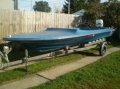
1969 Stern Craft Boat 19'( / Boats)

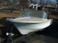
‘62 Dorsett Catalina( / Boats)


FiberGoogle
Who's Online
We have 9183 guests and one member online