Welcome, Guest
Username: Password: Remember me
  • Page:
  • 1

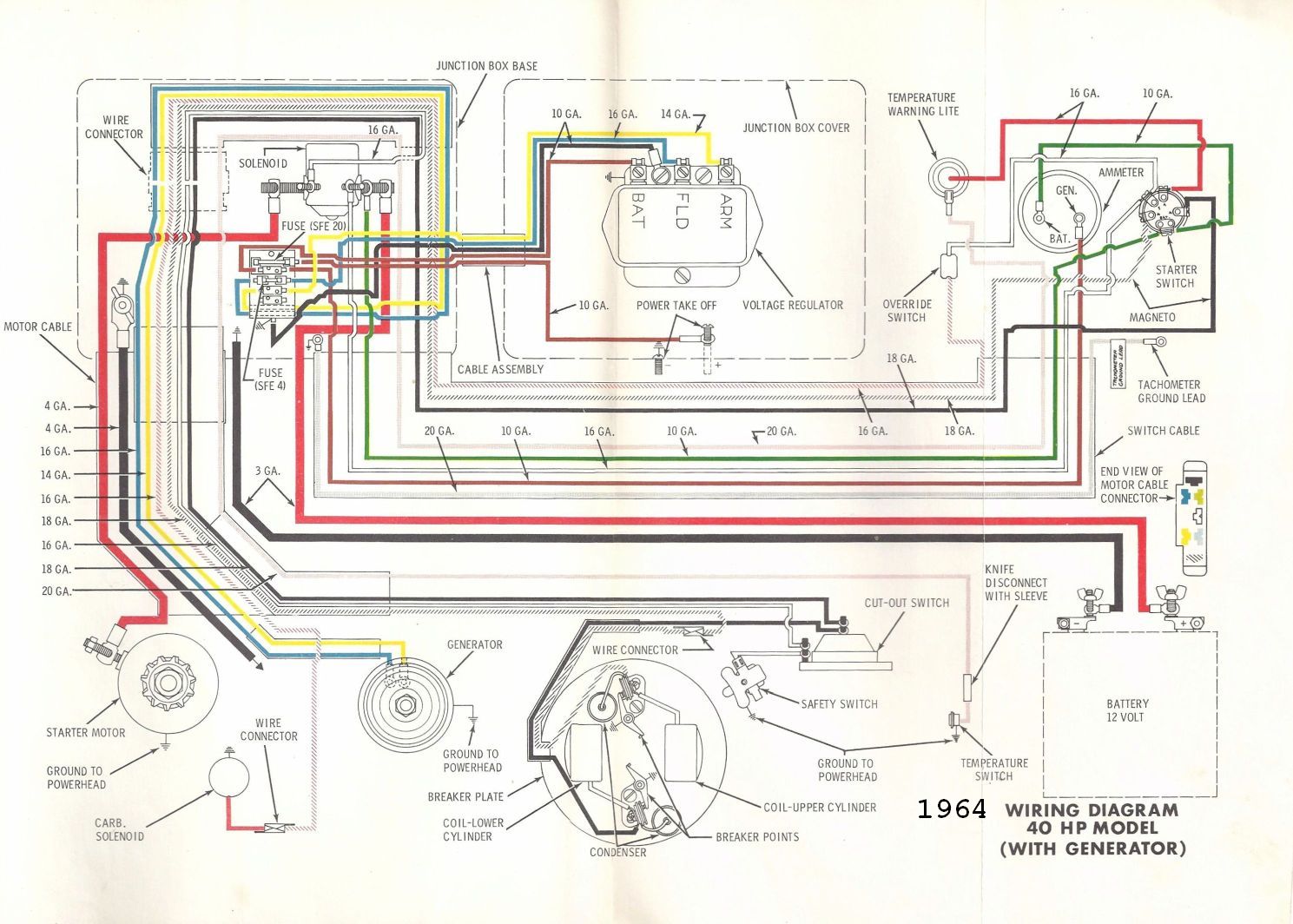
TOPIC: '63 40hp Big Twin Wiring Help Needed

'63 40hp Big Twin Wiring Help Needed 11 years 4 months ago #72406

I have purchased a magnificently restored ’63 Big Twin 40hp motor ( Model # 40353 D) and need some assistance with creating a wiring harness…and then attaching it. The manual I have only shows wiring for 40hp motors with a generator but I can’t identify anything on the motor that looks like it might be a generator. Any words of wisdom, diagrams, and/or witty comments would be much appreciated. -There should be some pictures of the motor and the manual wiring diagram attached.

Please Log in or Create an account to join the conversation.

Re:'63 40hp Big Twin Wiring Help Needed 11 years 4 months ago #72408

  • ed-mc
  • Away
  • Platinum Boarder
  • Platinum Boarder
  • Posts: 1391
  • Karma: 232
  • Thank you received: 113
Howdy, Bob, your motor doesn't have a generator, so your wiring needs should be minimal.

It looks like your motor doesn't have an electric choke solenoid & linkage installed, so you'll need to manual-choke or pick up the necessary parts to make it electric-choke. You can probably find parts on the Craigslist or on eBay.

I'm assuming you're mounting remote controls and want to be able to start the motor while seated in the driver's seat?

You can use separate starter and kill switches, but a 'cleaner' setup would be to mount a marine-style key switch in the dash to control those functions. You can get an ign switch that has the push-to-choke function as well, that way if you do ever install the electric choke parts, you won't have to install a separate switch for the choke.

Here's a nice dash-mount-style switch:

www.iboats.com/Ignition-Switch-ACCESSORY-OFF-RUN-START-7-Screw-Tab-Push-to-Choke-MarineWorks/dm/cart_id.355977380--session_id.735399099--view_id.62098

What you'll need for wiring is to extend the (2) wires currently connected to the pushbutton kill switch in the lower motor pan, up to the (2) "M" contacts on the ign switch.

The "M" contacts signify Magneto shorting and with the switch off, the (2) wires are shorted together which kills spark.

If you strip back a short length of insulation on each kill wire, and solder new wiring at that point, you can leave the wires hooked up to the kill switch on the motor pan and retain its function. Nice to have as a backup in an emergency.

For the starter, you're gonna need a suitable length of red battery cable, to connect directly to the starter and bring out to connect to a starter solenoid, on one of the larger terminals. You'll need another length of battery cable to connect to the other large terminal on the solenoid, and run over to the Pos terminal of the battery.

Run a length of black battery cable from the battery, to a grounding point on the motor. Typically you'd connect to one of the starter bracket bolts. Be sure to clean any paint off the connection point.

Most marine-type solenoids will have 2 small terminals. On a 2-terminal solenoid, one is connected directly to battery Negative terminal. I'd recommend 12-gage black wire for that but you could use 14-gage and it'll be fine.

Connect a yellow wire from the (other) small terminal on the starter solenoid, to the "S" contact on the ign switch. This provides +12V power to the solenoid with the ign switch in the "Start" position only.

Note: this power, of course, has to come from somewhere, so the last connection you'll need is to run a red, 12-gage wire from the Pos battery terminal to the "B" (Battery) terminal of the ign switch.

This'll provide power for the starter solenoid, choke switch, and any accessories you might want to add.

I'd recommend you install an inline fuse in this wire, 10-20 amps will do. You can pick up inline fuse holders at Radio Shack and other electronics/radio stores.

You'll have to decide how you want to mount the starter solenoid. Any type of enclosure that you can install under the motor splash well or somewhere at the stern near the battery, will do.

One last thought, you could make the installation a bit more "self-contained" by finding a spot inside the motor to mount the starter solenoid. There's quite a bit of room up front, to mount it on the pan. Just be sure to use a marine-grade solenoid, since they're sealed against the arcing of their contacts. Wouldn't want to blow up your nicely-restored motor!

Here's a compact, inexpensive starter solenoid that you could mount just about anywhere:

www.iboats.com/mall/partfinder/?cart_id=355977380&gd_grid_id=686&gd_poid=187763&gd_row=18&session_id=201037375

If I recall, some motors had a safety switch installed which you would connect in series with the grounded side of the solenoid control wiring. Can't tell if yours has that switch but I'd recommend hooking it up if it does, for safety's sake.

HTH.........ed

p.s., forgot to mention, you'll need to figure out where to run the cables into the motor, typically thru holes drilled in the lower pan, with rubber grommets inserted.

Please Log in or Create an account to join the conversation.

Re:'63 40hp Big Twin Wiring Help Needed 11 years 4 months ago #72410

Though they are for motors with generators, the following wiring diagrams may be of some use. The first is for the 1962 Big Twin standard shift w/ generator, the second is the 1964 Big Twin standard shift w/ generator.

You can ignore the voltage regulator as that is only needed for the generator. And that includes the blue and yellow wires of the charging circuit.


The most useful element of the 1964 diagram is that it shows which wire is which at the wiring connector. You may be able to splice into the existing powerhead wiring harness when making the new motor to dash harness.
Attachments:

Please Log in or Create an account to join the conversation.

Re:'63 40hp Big Twin Wiring Help Needed 11 years 4 months ago #72416

Ed and Andy - Thanks much for the quick reply and all the great information! I'm sure I'll have other questions and will definately post when it's all wired up. - Bob

Please Log in or Create an account to join the conversation.

Re:'63 40hp Big Twin Wiring Help Needed 11 years 4 months ago #72431

  • MarkS
  • MarkS's Avatar
  • Offline
  • Moderator
  • Moderator
  • Posts: 5348
  • Karma: 118
  • Thank you received: 5
Looks like a beauty Bob, good luck with it!

Please Log in or Create an account to join the conversation.

Mark

Re:'63 40hp Big Twin Wiring Help Needed 11 years 4 months ago #72475

Bob,

Those were very good engines, much stronger than the 1960 40 horse. The crankshaft on yours is more beefy at the top bearing than the earlier models. When run hard, the old style cranks could break at the flywheel snout.

The guys have given you some good info here, and I'd like to add some info that will help you figure out this project.

Let's start with the choke. You 40 originally had an automatic choke. This was a failry short lived idea at OMC, as an auto choke on a 2 cycle is pretty dang stupid. Someone has removed the schke stove and spring assembly from the carb on yours. You can see the mounting holes and the choke plate lever on the left side of the carb. I strongly encourage to swap the carb over to either an earlier model or later model with the electric choke. It is an easy direct bolt - on swap. The carb you have on there will not adapt to an electric - you need a different carb. They are very easy to obtain.

OMC electric starting engines originally had a remote mounted relay box to operate the starter, and to provide a junction box for all the electrical stuff. Since you engine was a later model, the bottom pan has a pass-thru for the electric harness. You are luck about that, because the earlier engines had a big rubber plag on the side of the motor - making any modifications very difficult. Forget about the remote relay box & put the starter relay under the hood. You can fabricate c bracket to mount one to & then bolt it to the engine. You can also search for a "bypass cover" off a later engine to mount the relay on. These covers had a special provision for mounting a starter relay - because OMC eventually quit using the remove relay box.

The hot ticket to making a nice wiring harness from the engine to the helm is to purchase heavy duty trailer light wiring. NAPA carries it in 5 and 7 wire configuration. It looks just like the original stuff, but it is vinyl so it will not rot like the old rubber did. All the wires are inside a black sheath. Very slick, and surprisingly inexpensive by the foot. I'd go for the 7 strand, that way you have a couple spare wires for a possible future need.

I think the gauge of the leads is 16, or it may be 14. Either way, it is more than ample to operate the starter relay and the choke solenoid. I've made tons of them & the work super.

This would allow you to run 2 main battery cables to the engine. The black (neg) connects to the bottom starter bracket bolt on the engine block. The Red (positive) connects to one of the starter relay studs. Run a short lead from the starter motor over to the other starter relay stud. Attach the red wire from your bundled wire harness to the (+) post on the start relay that goes to the battery. As mentioned above - putting a fuse between the small red wire and the (+) post of the start relay is a very smart idea. (You should have this fused)

Bundle the battery cables and the ignition switch harness together with electrical tape. A couple passes of tape is a good idea. This only needs to be taped from the inside of the hood to about a foot past the motor. These wires will drape onto the splashwell, and from there the main leads will go to the battery, and the harness will go to the helm.

At the ignition switch, hook the red wire to the "batt" terminal. This will now feed 12 volts to the rest of your engine functions needing it. At the motor - you can simply use crimp connectors to hook the various wires where they need to go. It will be easier to forget about the factory schematics and diagrams. They won't do you any good if you use the method I am suggesting. Remove ALL of the old wiring harness form the engine that is currently on it. I can assure you, that the way I'm suggesting will be the fastest and most simple way to go. Feel free to ask me for any tips if necessary.

Bruce G

Please Log in or Create an account to join the conversation.

Re:'63 40hp Big Twin Wiring Help Needed 11 years 2 months ago #74461

Bruce,

Thanks for the great advice. Sorry it has taken me so long to reply. I can hardly believe it's been more than two months since I last logged on...

Perhaps you can help me understand a little something more about the wiring for this motor.

I have wire and connectors, etc... and started working on a harness. Because I like to know as much about my toys as possible and I have a background in wiring stuff, I thought I should check for shorts and make sure I was hooking up the correct wires to the correct places.

The mystery I have is that the two wires that come down from the condensers (one that piggybacks onto the cutout switch) and are supposed to go to the 'M' terminals on the starter switch show continuity to each other and to ground. This is without being connected to the switch.

As I understand it, when connected to the switch, with the switch in the 'OFF' position, these two wires are shorted, resulting in the motor turning off. When the switch is moved to the 'ON' position, the wires are no longer shorted which allows the motor to start.

There is/was a manual cut off switch installed (in the picture those are the leads with the blue quick disconnects attached). I removed it for testing. There are three wires going into the molex connector. The two black wires are solder spliced to the leads coming from the condensers. The white wire, I think, is supposed to be a connection to an overtemp warning light. It goes back to a small hole at the back of the motor.


_________________________________________________________________


So the question: If the leads from the condensers are shorted to each other and to ground, does that mean I'm going to have pull the flywheel to get at the vacuum cutoff switch and condensers to look for a short? Does this mean the vacuum cutoff switch is bad (not the aftermarket kill switch which is not currently connected)?Or, is this the way it's supposed to be and I'm misreading the manual?

About the vacuum cutoff switch...where the heck is it? The Seloc manual doesn't say and I can't find any resource on line that does. I have been unsuccessful at identifying anything on the motor that resembles its 'icon' in the manual and in on-line resources. If you've got a copy of manual # 1300, it's briefly mentioned in chapter 5 on pages 6 and 7.

Some additional info:
The motor has no external wiring currently attached, nor has it since I got it. I just started working on building the wiring harness. Since it has been in my posession (late last July), it has never been connected to battery or fuel. I metered those leads at least a dozen times, checking for any breaks in the insulation, making sure the solder splice wasn't touching the motor body, etc... If there is a break in in the insulation it is somewhere I can't see and my fingers can't reach.

Looking forward to hearing back from you (or anyone else). I would dearly love to put a functioning boat on the water this Spring.

Best,
Rob
Attachments:

Please Log in or Create an account to join the conversation.

Re:'63 40hp Big Twin Wiring Help Needed 11 years 2 months ago #74479

I'm finding information here that will benefit me also. Although mine is earlier. Also when I had my old ATV the ignition switchs were very expensive. So I went to tractor supply and got a cheap tractor ignition and mounted it so the water did not lay on the keyhole. Even though it had an internal slot cover. I used that thing in mud that came over the fender tops. When I sold it it still had that ignition switch. I was planning on having another starter button hidden by the outboard and just choke it from there. My choke is not any electric to it. Mine does have that square box plug in that I want to find. I'm looking for a donor boat around here.

Now remember this switch is steel. I put graphite inside mine and coated the outside to make it more water proof. And it seem more wetness on my atv than it would in MY boat. It does not sit in the water or weather as far as that goes. It sits in my carport. It does have the turn to start option eliminating a separate starter button.
www.tractorsupply.com/conduct-tite-starter-switch-key-style-metal-1042039
If not for marine use I would recomend it anywhere else.
Attachments:

Please Log in or Create an account to join the conversation.

Re:'63 40hp Big Twin Wiring Help Needed 11 years 2 months ago #74490

The " cutout switch " should be mounted on the side of the block.--Obviously it is missing.
The hot water choke set-up is also missing.
Have you done a compression test on this motor ??

Please Log in or Create an account to join the conversation.

Re:'63 40hp Big Twin Wiring Help Needed 11 years 2 months ago #74494

Prof - Which side of the block should the vacuum cutoff switch be mounted? And the "hot water choke setup", should that be attached to the carb or the block?

Haven't done a compression test yet. Was lead to believe when I bought the motor it was good to go and just needed controls and wiring harness hooked up.

I could really use an answer on why the switch leadds coming down from the condensers are shorted to each other and what kind of rabbit hole that opens up for me.

Thanks for the comments. Food for thought.

Please Log in or Create an account to join the conversation.

Re:'63 40hp Big Twin Wiring Help Needed 11 years 2 months ago #74513

I think a compression test should be done first or inspect pistons and rings via the 2 tranfer port covers on the side of the motor.
6 screws each and 2 cheap gaskets.

Please Log in or Create an account to join the conversation.

Re:'63 40hp Big Twin Wiring Help Needed 11 years 2 months ago #74589

I agree that a compression test is in order but I don't understand how it will answer the question of why the leads from the condensers are shorted to each other. That's the issue holding up completion of the wiring harness...Anybody have ant thoughts?

Please Log in or Create an account to join the conversation.

Re:'63 40hp Big Twin Wiring Help Needed 11 years 2 months ago #74605

To me there are too many things that are " wrong " on this motor.
Do a compression test !!

Please Log in or Create an account to join the conversation.

Re:'63 40hp Big Twin Wiring Help Needed 11 years 2 months ago #74635

Prof - I don't understand how compression is related to the wiring issue. If the matter was that the engine wouldn't start or ran poorly, I would get it, but I haven't even tried to start it yet. Just trying to hook all the wires up properly and to make sure I don't blow up her electrical on the first go.

I'm already vested in all the wire, starter switch, solenoid, etc... so it's not a matter of buying or not buying materials.

I understand why not having the cut-out-switch in place is an issue and will endeavor to correct that as I progress.

Could you give up a little more info for this newbie?

Thanks - DB

Please Log in or Create an account to join the conversation.

  • Page:
  • 1
Time to create page: 0.294 seconds

Donate

Please consider supporting our efforts.

FG Login

Glassified Ads

Gator 9" wheels Wanted
( / Wanted)

noimage
04-24-2024

1969 Stern Craft Boat 19'
( / Boats)

1969 Stern Craft Boat 19'
04-08-2024

‘62 Dorsett Catalina
( / Boats)

‘62 Dorsett Catalina
04-08-2024

FiberGoogle

Who's Online

We have 8949 guests and 3 members online