Welcome, Guest
Username: Password: Remember me
  • Page:
  • 1

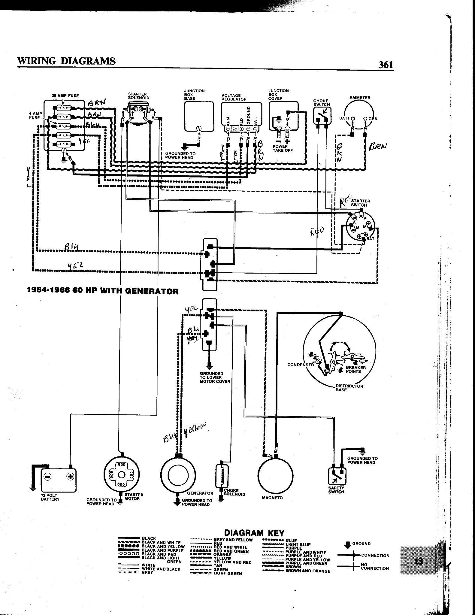
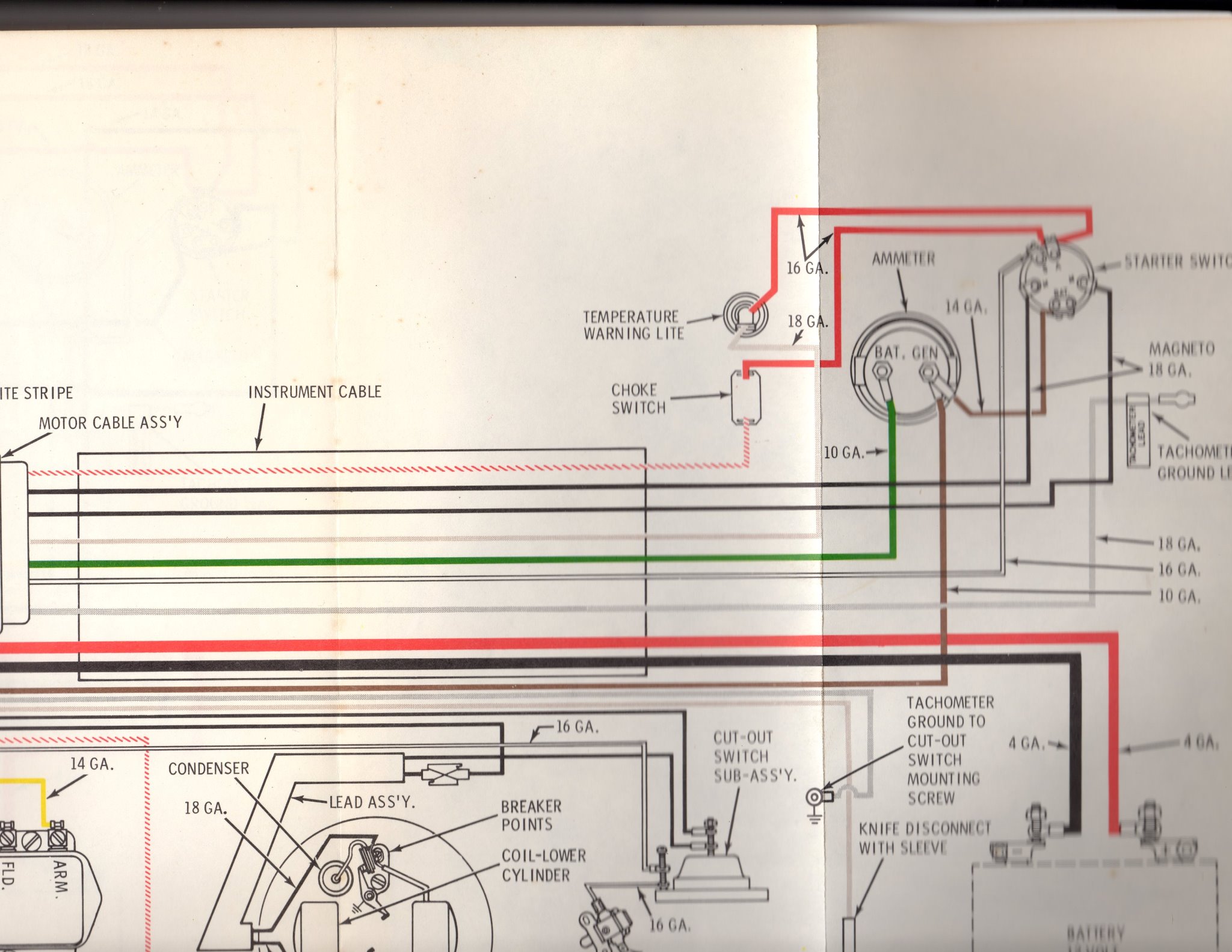
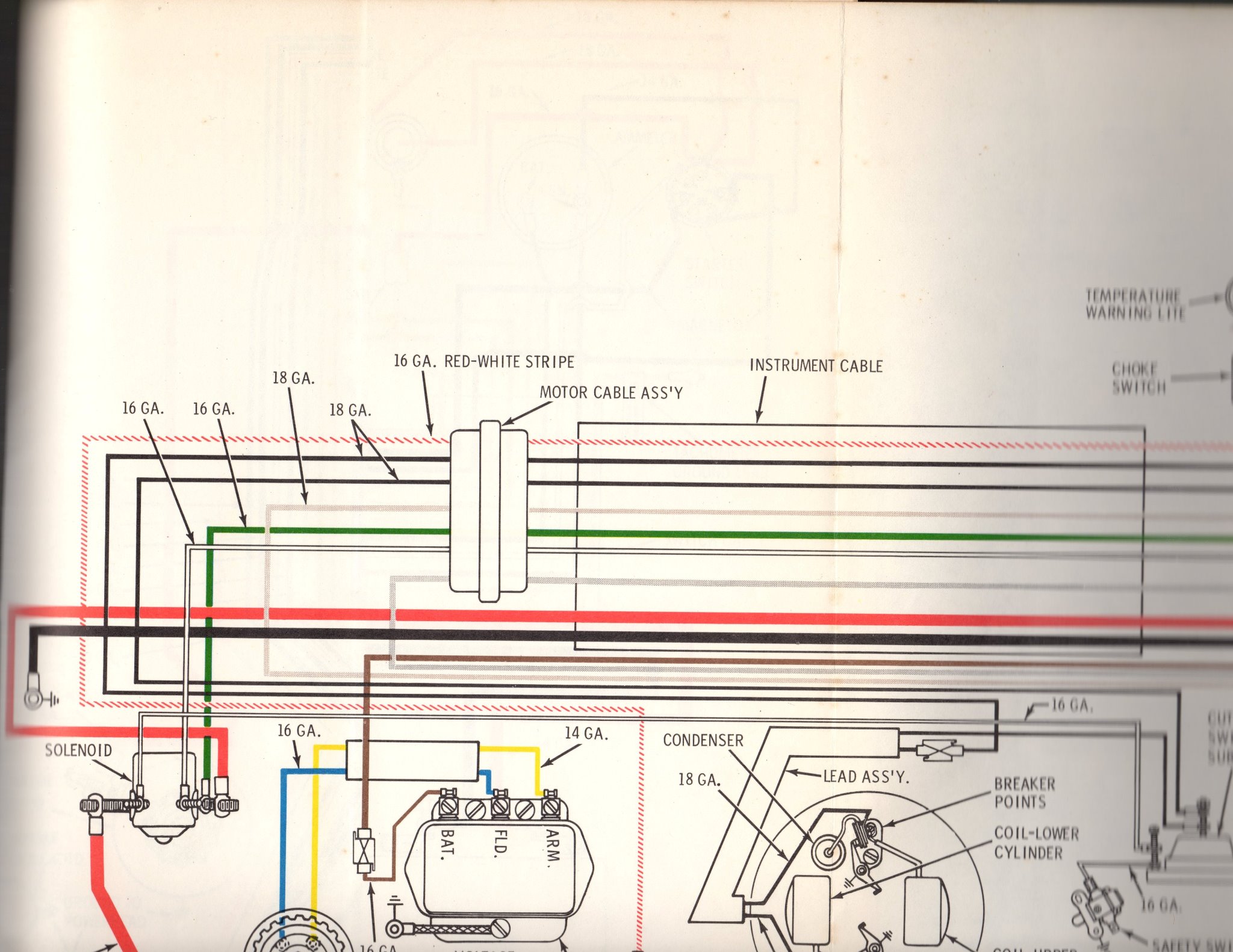
TOPIC: mispost on ampmeter

mispost on ampmeter 6 years 10 months ago #132363

  • 63 Sabre
  • 63 Sabre's Avatar Topic Author
  • Offline
  • Contributing Member
  • Contributing Member
  • Posts: 4676
  • Karma: 147
  • Thank you received: 167
Posted on the wrong forum about ammeter wiring. Wound up in the main forum. Anyone read it??

Please Log in or Create an account to join the conversation.

mispost on ampmeter 6 years 10 months ago #132400

  • 63 Sabre
  • 63 Sabre's Avatar Topic Author
  • Offline
  • Contributing Member
  • Contributing Member
  • Posts: 4676
  • Karma: 147
  • Thank you received: 167
Still having problems with my charging circuit on the 60hp 1965 Evinrude with generator.
The amp meter is wired up according to the Clymer schematic with the green wire from the battery connected to the (+) side of the meter and then a jumper connects to the "batt" on the ignition switch. ... Doesn't work.
I also have a service manual supplement for a 1967 that has the wiring different. On that schematic it shows the brown wire from the voltage regulator "batt"going to the (-) side of the amp meter and then a jumper wire going to the ignition "batt".
Which one is right??? It boils down to that little jumper wire to the ign switch. Should it be from the + side of the meter or the - side of the meter.
Attachments:

Please Log in or Create an account to join the conversation.

mispost on ampmeter 6 years 10 months ago #132409

Go with the factory manual supplement. Clymer manuals suck.
The following user(s) said Thank You: 63 Sabre

Please Log in or Create an account to join the conversation.

mispost on ampmeter 6 years 9 months ago #132415

Both diagrams will work, but I believe the 1967 one is the better of the two.
The basic flow in the 64-66 diagram is generator to ammeter to ignition switch. The flow in the 67 diagram is generator to ammeter GEN terminal where it is divided. Battery charging current goes through the ammeter and light and accessory current goes to the ignition switch.
The 64-66 diagram routes ALL CURRENT being produced by the generator through the ammeter, including any lights or accessories being used. Some early car ammeters were wired this way.
The 67 diagram only runs the CURRENT BEING SENT TO THE BATTERY through the ammeter. Any current for lights or accessories is sent to the ignition switch and not through the ammeter.
The advantage to this method is that the ammeter will show zero charge when the battery is fully charged. If you see a constant positive charge it indicates a possible problem with the battery or regulator.
The following user(s) said Thank You: 63 Sabre

Please Log in or Create an account to join the conversation.

mispost on ampmeter 6 years 9 months ago #132416

  • 63 Sabre
  • 63 Sabre's Avatar Topic Author
  • Offline
  • Contributing Member
  • Contributing Member
  • Posts: 4676
  • Karma: 147
  • Thank you received: 167
OK, thanks guys. All I really have to do is switch that jumper wire from the + to the - side of the meter. I do have a digital readout volt meter and it always shows a steady 12.4 to 12.8 volts on my new battery so I really shouldn't see any movement in the amp meter.

Please Log in or Create an account to join the conversation.

  • Page:
  • 1
Time to create page: 0.179 seconds

Donate

Please consider supporting our efforts.

FG Login

Glassified Ads

FiberGoogle

Who's Online

We have 6695 guests and one member online