Welcome, Guest
Username: Password: Remember me
  • Page:
  • 1

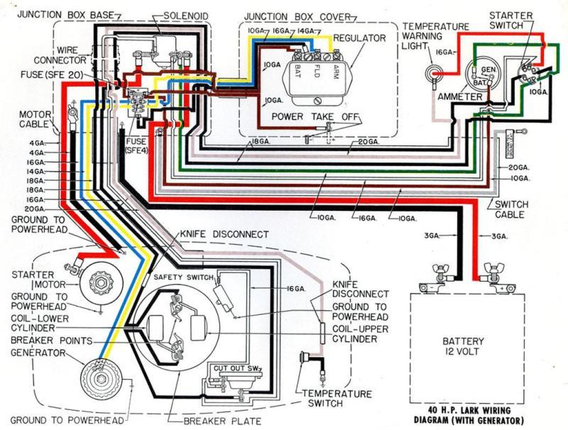
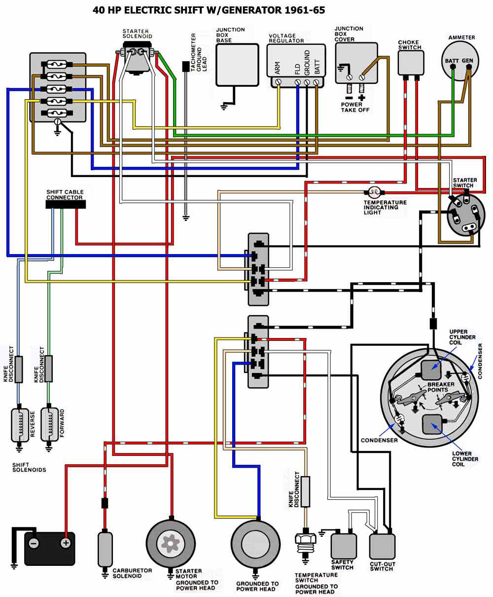
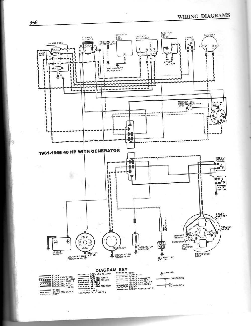
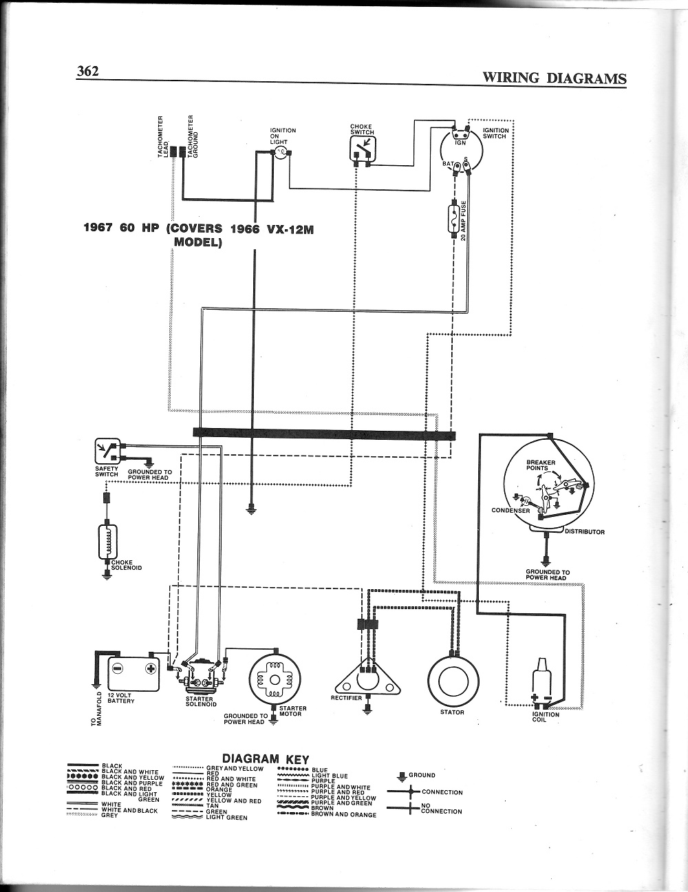
TOPIC: tach signal wire - '64 Lark VI

tach signal wire - '64 Lark VI 9 years 6 months ago #100608

  • Eric Z
  • Eric Z's Avatar Topic Author
  • Offline
  • Contributing Member
  • Contributing Member
  • Posts: 237
  • Karma: 2
  • Thank you received: 19
Hi,

Can anyone help with this? I received a replacement retro style tach that replaces the same version originally in the boat. It is a SUN FZ88R www.sunpro.com/product_category.php?id=377

There are 4 terminals on the back of the tach;
Ground wire
Signal wire
+ 12 v wire
Light wire

I see on the attached wiring diagram for my 1964 2 cycle Evinrude Lark VI 40 HP with generator that the ground wire is a gray 20 awg to the right.

Where does the signal wire connect to?

Thanks
Attachments:

Please Log in or Create an account to join the conversation.

Re:tach signal wire - '64 Lark VI 9 years 6 months ago #100624

  • 63 Sabre
  • 63 Sabre's Avatar
  • Offline
  • Contributing Member
  • Contributing Member
  • Posts: 4676
  • Karma: 147
  • Thank you received: 167
Welcome aboard.
I did some searching and found this link which might be helpful. You have to page down to the comments. Looking at a few other sites it sure sounds like the gray wire is your signal wire not ground.
In the schematics ground wire is black.

www.instructables.com/id/Automobile-Tachometer-on-an-outboard/

The schematics I have do not show complete wiring diagrams for a tach on a '64, closest I have is for a '66 60 hp model and the grey tach wire connects to the coil negative (-).

Please Log in or Create an account to join the conversation.

Re:tach signal wire - '64 Lark VI 9 years 6 months ago #100625

  • Eric Z
  • Eric Z's Avatar Topic Author
  • Offline
  • Contributing Member
  • Contributing Member
  • Posts: 237
  • Karma: 2
  • Thank you received: 19
thanks for the reply. The sun unit I have is slightly different and actually has the setting for a 2 stroke so the resistor issue won't come into play. I found another schematic that also shows the gray wire as the ground, terminating at the junction box. see below, but no mention of the signal wire.
Attachments:

Please Log in or Create an account to join the conversation.

Re:tach signal wire - '64 Lark VI 9 years 6 months ago #100632

tabbs creek,

WELCOME ABOARD.

yours, satx

Please Log in or Create an account to join the conversation.

Resistance to tyrants is obedience to Almighty God.
Thomas Jefferson, 1803

Re:tach signal wire - '64 Lark VI 9 years 6 months ago #100634

  • 63 Sabre
  • 63 Sabre's Avatar
  • Offline
  • Contributing Member
  • Contributing Member
  • Posts: 4676
  • Karma: 147
  • Thank you received: 167
Just sayin'.
Here are two schematics that I have. The one for the 40 hp is a conundrum. Like your pictures it actually shows nothing. Grey wire to ground. If that's the case what will you do with the ground wire?
Light=easy
12v=easy
grnd=easy
Signal wire doesn't leave much for debate does it.

The second schematic actually shows where the wires go, at least on the 60 hp.
Attachments:

Please Log in or Create an account to join the conversation.

Re:tach signal wire - '64 Lark VI 9 years 6 months ago #100635

  • Eric Z
  • Eric Z's Avatar Topic Author
  • Offline
  • Contributing Member
  • Contributing Member
  • Posts: 237
  • Karma: 2
  • Thank you received: 19
Well, there is no ignition coil shown on the 40 HP diagram but both 40 & 60 have the condenser and breaker points shown which on the 60 tie to the signal wire and on the 40 tie back to the black and white dashed wire at the ignition switch. What do you think; would the signal be available at the black & white dashed wire on the switch?

Someone else thought bringing it to the green battery lead on the amp meter would pick up the pulse??

sorry, I'm a novice and don't want to screw it up!

Please Log in or Create an account to join the conversation.

Re:tach signal wire - '64 Lark VI 9 years 6 months ago #100642

tabbs creek,

I think it would be helpful if we knew more about the tach you have. I went to the link you had and the info I could find for your model was basically sales literature.
Did you get an installation manual?
The Sun tachs, like most early tachs measured the pulse generated when the points opened and closed. The points had 12 volts when they were open and 0 volts when closed.
Then to make them compatible with 4,6, and 8 cylinder engines they usually had a switch or various jumper wires that would be connected to fit the engine you used it on. Some of the cheaper tachs only worked with only one version of engine.
When electronic ignitions came along tach manufactuerers switched to other methods of pulse measurement. Some went with alternator pulses and they had to be set to the number of poles (pulses) of the engine alternator. Other systems could be wired in to the electronic ignition. Most would not work with point systems.
It appears you have a new repop Sun tach. Is there any information that it will work with point or magneto ignition? Then the next issue, pointed out in a previous post, is that your Lark's ignition is backwards. It's actually more like a magneto. It makes it's own power and it has to be grounded to stop the engine. That usually rerquires a tach designed to work with that system.
Then there is the generator. You do not have an alternator for pulse count so I don't believe that style of tach will work.
Also, you mention a two stroke setting. How is that done? Jumper connections or a switch?
That has to be done because a the two stroke fires every stroke and the four stroke, every other so if you are counting firing pulses you need to tell the tach what the engine is.
The diagrams are a bit puzzling. The 61-66 shows a dedicated tach ground wire that goes through the wire loom to ground in the powerhead. This is probably done to get a cleaner ground. There is no other wiring for the tach shown.
The 1966 also has a dedicated tach ground to the powerhead, but it is routed to the ignition on light and then on to the powerhead.
The 1966 however has different ignition system. It uses a single coil, a distributor, and a pair of points wired in parallel.
It has a tach signal circuit hooked to the negative of the coil and then is routed to the tach. This is the same as old point operated automotive ignition systems.
Any old automotive tach would work with it as long as can have the cylinder count set properly.
Is it possible to post the instructions or link to them. It would really help.

Don

Please Log in or Create an account to join the conversation.

Re:tach signal wire - '64 Lark VI 9 years 6 months ago #100646

  • Eric Z
  • Eric Z's Avatar Topic Author
  • Offline
  • Contributing Member
  • Contributing Member
  • Posts: 237
  • Karma: 2
  • Thank you received: 19
Hi Don,
Yes here are the 2 page instructions. General info states 4 cylinder and page 2 has several references to the 2 cycle setting for the dip switch. The original sun tach had the same 2 cylinder setting, unfortunately the wires were disconnected when I purchased the boat.

The section in bold "multiple spark discharge ignition system equipped engines" could be the correct method?

The 5 poles on the rear of my cole hersee switch going clockwise are;
IGN
MAG
BAT
MAG
ST

So would that make the BAT terminal the destination for the signal wire? (if this is the correct scenario)

Thank you

Please Log in or Create an account to join the conversation.

Re:tach signal wire - '64 Lark VI 9 years 6 months ago #100647

  • Eric Z
  • Eric Z's Avatar Topic Author
  • Offline
  • Contributing Member
  • Contributing Member
  • Posts: 237
  • Karma: 2
  • Thank you received: 19
page 1
Attachments:

Please Log in or Create an account to join the conversation.

Re:tach signal wire - '64 Lark VI 9 years 6 months ago #100648

  • Eric Z
  • Eric Z's Avatar Topic Author
  • Offline
  • Contributing Member
  • Contributing Member
  • Posts: 237
  • Karma: 2
  • Thank you received: 19
page 2
Attachments:

Please Log in or Create an account to join the conversation.

Re:tach signal wire - '64 Lark VI 9 years 6 months ago #100671

tabbs creek,

According to the instructions it doesn't look like that tach will work with your motor. There is no reference anywhere in the docoument that mentions two stroke applications, however the first paragraph on page one says the tach is designed for "12-volt negative ground, 4-cycle engines".
All the applications shown either require a distributor, which your motor does not have, or a tach lead from an electronic (MSD, CD, coil on plug) system. You have a magneto system.
Now I know tachs have been built for your system, Airguide built them for many years, and your motor has a tach ground lead, so the tach you have could possibly work with this system, but without diagrams of the actual internal ignition coil wiring (auto or standard transformer) and the required input for the tach sensing circuit, it's diffcult to determine.
At this point you may want to contact SunPro.

Technical Support group at This email address is being protected from spambots. You need JavaScript enabled to view it. or call us toll-free at
1-800-228-7667.

Tell them you have a 2 stroke, two cylinder outboard with a magneto using two points and two flywheel coils with shutdown circuits to your key switch. Those should be the two black wires on the MAG terminals.
Even though the instructions don't specifically mention two stokes, I am guessing that the tach might work as most modern electronics have a lot of built in capabiblity that even the marketing people in the company are unaware of. Your motor does have a pulsing lead at the ign switch. The question is, is your tach capable of reading it?
If SunPro mentions the difference between 2 stroke and 4 stoke firing pulses, ask if you just sense one cylinder why can't you just switch to the 2 cylinder position.

Don

Please Log in or Create an account to join the conversation.

Re:tach signal wire - '64 Lark VI 9 years 6 months ago #100673

  • Eric Z
  • Eric Z's Avatar Topic Author
  • Offline
  • Contributing Member
  • Contributing Member
  • Posts: 237
  • Karma: 2
  • Thank you received: 19
Thanks Don,I actually contacted them first and they were of no help. I'll go back and try again. I appreciate your input.

Please Log in or Create an account to join the conversation.

Re:tach signal wire - '64 Lark VI 9 years 6 months ago #100674

tabbscreek,

OK, if you can't get any help from SunPro this time, I do have an idea how to make it work. (See disclaimer below)
There should be two black wires going to the MAG terminals on the keyswitch, or, one may be black and the other black and white.
Hook up the power and ground on the tach. Move the cylinder switch to 2 cylinder position. Start and let the motor warm up and then idle.
Now take the sense wire and momentarily touch it to either black/white wire, or either of the black ones if that is what you have. You can use an alligator clip to make it easier.
You should see the tach show from 600-1000 RPM. If so, continue to hold or clip the sense wire on the black/white or black wire and speed up the engine. The tach should follow the speed. If it does, start and stop the engine a couple of times to make sure the tach goes to 0 and operates again after restart. If it works OK, hook it up permanently.
As I mentioned above, those wires have a pulse, it's just a question if the tach will read it correctly.
DISCLAIMER: I think that a modern tach would have enough built in safeguards to combat indiscriminate wire switching and reverse polarity, but there is the chance that trying the above test could toast the tach.
Don't know how bad you want it to work, or how much you have invested in it so it's your call.

Don

Please Log in or Create an account to join the conversation.

  • Page:
  • 1
Time to create page: 0.224 seconds

Donate

Please consider supporting our efforts.

FG Login

Glassified Ads

FiberGoogle

Who's Online

We have 6523 guests and no members online